CV Series User Manual This User Manual is made available in Adobe Acrobat format. In order to view the manual and utilize it’s enhancements we recommend that you download Adobe Acrobat Reader® 4.0 or greater. If you do not currently have this viewer installed on your computer, or you have an older version the reader is available as a free download at http://www.adobe.com. By going to the table of contents you can directly access any topic outlined there, by simply clicking on the topic.
SAFETY INFORMATION The lightning flash with arrowhead symbol within an equilateral triangle is intended to alert the user to the presence of uninsulated “dangerous voltage” within the product’s enclosure that may be of sufficient magnitude to constitute a risk of electric shock to persons. CAUTION RISK OF ELECTRIC SHOCK DO NOT OPEN CAUTION: TO REDUCE THE RISK OF ELECTRIC SHOCK DO NOT REMOVE COVER. NO USER SERVICABLE PARTS INSIDE.
INTRODUCTION Congratulations on your purchase of a new Carver Professional CV Series Power Amplifier. The CV Series amplifiers are designed expressly for commercial and institutional audio applications. The CV Series amplifiers are designed and manufactured by Carver Professional, a division of Phoenix Gold International, Inc. They combine Carver Professional’s experience in pro audio along with the needs of the system integrator to provide an uncompromising product for the commercial sound industry.
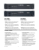
CV1501 CV2501 Power Output Power Output • 150W mono into 4 ohm and 8 ohm loads, autoformer coupled, 40Hz to 20kHz ±3db with < 0.5% THD at full power • 250W mono into 4 ohm and 8 ohm loads, autoformer coupled 40Hz to 20kHz ±3dB with < 0.5% THD at full power • 150W mono transformer coupled @ 25V, 35V, 50V, 70V and 100V 40Hz to 18kHz ±3dB with < 0.5% THD at full power • 250W mono transformer coupled @ 25V, 35V, 50V, 70V and 100V, 40Hz to 18kHz ±3dB with < 0.
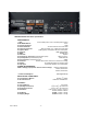
SPECIFICATIONS with Basic input module PERFORMANCE: • THD: <0.5% @ rated power, 0.2% 1/8 rated power at1 kHz • IMD DIM30 Method: <0.2% • Dynamic Headroom: 1.5dB • Power Bandwidth: 40 Hz to 20 kHz, 4 and 8 ohm loads • Frequency Response: 30 Hz to 20 kHz +0.5, -3dB(4 and 8 ohm loads) • Signal-to-Noise: 94dB (typical), A-weighted, referred to rated power • CMRR: 75dB at 1kHz • Slew Rate: 7V/µSec • Sensitivity for rated power (includes EFX Inputs): 0dBu or 0.
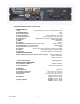
CV1502 CV2502 Power Output Power Output • 150W per channel into 4 ohm and 8 ohm loads, autoformer coupled, 40Hz to 20kHz ±3dB with < 0.5% THD at full power • 250W per channel into 4 ohm and 8 ohm loads, autoformer coupled, 40Hz to 20kHz ±3dB with < 0.5% THD at full power • 150W per channel, transformer coupled @ 25V, 35V, 50V, 70V and 100V, 40Hz to 18kHz ± 3dB with < 0.
SPECIFICATIONS with Basic input module PERFORMANCE: • • • • • • • • • • • • • • • THD: 0.5% at rated power, 0.2% at 1/8 rated power at 1kHz IMD DIM30 Method: <0.2% Dynamic Headroom: 1.5dB Power Bandwidth: 40 Hz to @20 kHz +0.5, -3 dB Frequency Response: 26 Hz to 20 kHz, 4 and 8 ohm loads Signal-to-Noise 94dB (typical), A-Weighted, referred to rated power Crosstalk: -60dB, full bandwidth CMRR: 75dB at 1kHz Slew Rate: 7V/µSec Sensitivity for rated power (includes EFX Inputs): 0dB or 0.
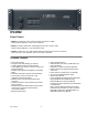
CV4002 Power Output • 400W per channel into 4 ohm and 8 ohm loads, autoformer coupled, 40Hz to 20kHz ±3dBwith < 0.5% THD at full power • 400W per channel, transformer coupled @ 25V, 35V, 50V, 70V and 100V, 40Hz to 18kHz ±3dB with < 0.5% THD at full power • 800W in parallel mono at 4 Ohms, 800W parallel and bridged mono at 8 and 16 Ohms, 50V, 70V, 100V, 140V and 200V, with no more than 0.
SPECIFICATIONS with Basic input module PERFORMANCE: • • • • • • • • • • • • • • • THD: 0.5% at rated power, 0.2% at 1/8 rated power at 1kHz IMD DIM30 Method: <0.2% Dynamic Headroom: 1.5dB Power Bandwidth: 40 Hz to 20 kHz 4 and 8 ohm loads Frequency Response: 26 Hz to 20 kHz +0.5, -3 dB 4 and 8 ohm loads Signal-to-Noise 94dB (typical), A-Weighted, referred to rated power Crosstalk: -60dB, full bandwidth CMRR: 75dB @ 1kHz Slew Rate: 7V/µSec Sensitivity for rated power (includes EFX Inputs): 0dB or 0.
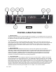
Figure 1 CONTROLS AND FUNCTIONS 1. Rack Mount Ears The ears for rack mounting the CV Series amplifiers are removable. If your installation does not require rack mounting, the rack ears can be removed, however the screws that fasten the rack ears to the chassis should be replaced to maintain the chassis’ structural integrity. 2.
Figure 2 5. CV Series Model Number The Model number should be interpreted as follows: The last digit of the model number designates the number or channels or zones supported by the amplifier. The digits preceding the last digit designate the rated output power of a channel or zone for that amplifier. The CV Series amplifiers are a constant voltage design, and have the same output at 4 ohm, 8 ohm, 25V, 35V, 50V, 70V and 100V taps.
Figure 3 1. Serial Number The Serial Number is used by Carver Professional to track units and establish their warranty status. Be sure to record the serial number of all Carver Professional units, and to keep those records in a safe and secure location for future reference. Never remove the serial number, as this will void the warranty. 2. Output Connector The Output Connector is a special non-shorting Euro Connector utilized for safety purposes.
4. Remote Level The Remote Level Connector is used to connect a Remote Level Control to the CV Series amplifier. The connector is a Euro Style connector with the following connection points, from left to right. (See Figure 5) RTN – Return, CV2 – Control Voltage for Channel 2 on Dual Channel models, CV1 – Control Voltage for Channel 1, and +5V volt send from the VCA package. More information on how to connect this feature is available later in this manual Figure 5 5.
CV Series amplifier. If your application requires rack mounting, optional line cords, shorter than the standard 2 meter, are available as accessory item for the CV Series amplifiers. 9. Configuration DIP Switches Each CV Amplifier channel can be individually configured via the DIP Switches on the rear panel.
amplifier’s chassis structure to the rear of the rack during transportation. This practice is recommended for all electronic components. Thermal Considerations When the CV Series amplifiers are used free standing, no thermal considerations are necessary other than using the four rubber feet supplied with the amplifier. This raises the amplifier above the surface it is sitting on enough to allow free movement of air through the heatsink located along the left side of the amplifier.
Another input to the CV Series amplifiers is provided via the EFX Loop’s RCV (receive) input. This input is only available when the FX Loop is enabled on the DIP switch located on the rear of the amplifier. This input is designed for unbalanced line level input only, and should only be used with equipment that is local to the CV amplifier or rack containing the CV amplifier, such as, an outboard signal processing device or the SND output from the FX Loop on the same or another (local) CV amplifier.
output of the CV2502 to create a Mono 70V output at 500 Watts. Connect the positive (+) lead from the distributed load to the 35V connector on Channel 2, and connect the negative (-) lead from the distributed load to the 35V connector of Channel 1. Be sure that the sum of the output to each of the speakers on the distributed load is less than 500 watts. (See Figure 8) It is also necessary to connect the commons together when bridging a distributed load.
Important Note: When bridging the CV Series amplifier at one of the distributed voltage outputs, it is necessary to connect the Common connections for the distributed voltages together. The commons on the secondary side of the output transformers are floating. This is not true for the low-impedance outputs. Their respective commons are connected internally.
amplifiers in the sequence are connected. Connect the negative side of the DC supply to the chassis ground terminal. If the amplifiers are mounted together in a rack where a common AC Ground connects the chassis grounds together through common connection via the metal rack rail, no other connections should be required. (See Figure 10) If this is not the case, simply connect all of the “Chassis Ground” terminals together.
Using Other Amplifiers in the Power Sequence The Carver pm700, pm950, pm1400, pt1800 and pt 2400 can be use together with the CV Series amplifiers in a “Sequenced” configuration. However, as the Sequence Terminal on the pm Series has no Chassis Ground connector, whenever this manual references the chassis ground connector you should replace it with some reliable ground connection point on the PM series amplifier chassis such as a screw that is used in fastening the chassis parts together.
and CV2 terminals. If you wish to control both channels simultaneously, using the remote control as a master level control and the front panel level controls as balance adjustments, both control inputs may be connected together and driven off the wiper of a single pot. (See figure 15) An example of this application would be in a system where the CV Series amplifier is being used to reproduce stereo information, and keeping two level controls synchronized during adjustment would be difficult.
Using Third Party Control Systems Other manufacturers such as Crestron®, AMX® and PANJA® supply systems frequently used to provide a centralized control platform for A/V Systems. A voltage ramp provided by one of these manufacturers, and controlled by their system can be used to adjust level on the CV Series amplifiers. Apply a control voltage from the external source of the desired control system to the “Remote Level” input terminal.
WARRANTY INFORMATION CV Series Power Amplifiers: 5 Years CV Series Modules and Accessories: 1 Year NOTE: The following warranty is exclusive to the United States and its possessions and territories. Please see your Carver Professional dealer or distributor for the correct warranty information in your area or locale. WHAT IS COVERED: THIS WARRANTY COVERS DEFECTS IN MATERIAL AND WORKMANSHIP ONLY.
CARE AND SERVICE ASSISTANCE Care: Wipe off the CV Series Amplifier’s front panel and chassis from time to time, with a soft, dry cloth. If you have something stubborn to remove, use a mild dish soap or detergent sparingly applied to a soft cloth. Don’t use alcohol, ammonia or other strong solvents. Service Assistance: We suggest that you read the Limited Warranty completely to fully understand your warranty/service coverage. Please promptly complete and return the Warranty registration card.
Distortion Distortion is usually caused by excessive loss in the input controls (the mixer/equalizer/crossover cannot produce enough output), overdriving resulting in output clipping, or current limiting caused by excessively low load impedance. 1) Check the setting of the input level controls. If set too low, the preceding piece of equipment may not have sufficient output to overcome the loss.
Appendix “A” Power Consumption for CV Series Amplifiers CV Series AC Power Considerations Model CV1501 CV2501 CV1502 CV2502 CV4002 Model CV1501 CV2501 CV1502 CV2502 CV4002 Model CV1501 25v tap CV2501 25v tap CV1502 25v tap CV2502 25v tap CV4002 35v tap Model CV1501 25v tap CV2501 25v tap CV1502 25v tap CV2502 25v tap CV4002 35v tap Rev 04.08.021 1kHz Sine Wave @ Full Rated Power into 4 Ohm Autoformer Winding 100vAC (50Hz) 100vAC (60Hz) 120vAC (60Hz) 230vAC (50Hz) 250 Watts / 3 Amps 249 Watts / 2.
Appendix “B” Input Sensitivity Jumpers 101 and 102 on the standard input module’s PCB are used to set the Input Sensitivity of the amplifier for each channel or zone. The output level of the input source determines the setting. Since, each channel or zone may have a different input source, it is acceptable to have these jumpers set differently according to the potential output level of the input source. The figure below show the correct jumper setting for an input sensitivity of 0.775VRMS or 1.5VRMS.