
Owner's Manual

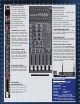


25. MONO/SUB CONTROL
A mono output is created from the
L/R
master
faders (post) for center, subwoofers, or side fill
speakers. The output is at the MONO/SUB XLR
connector (#37).
26. HEADPHONE/METER SOURCE
The stereo PHONES control sets the level of the
PHONES jack (#35). The L/R, MONO, MON 1-4 &
SUB 1-4 switches allow for monitoring of these
sources through the headphones and see the
levels on the L/R LED METERS (#28).
27. PFL RED LED
Indicates that the headphone & meters are monitor-
ing only the channels or groups where the PFL is
switched on.
28. L/R LED VU METERS
This group of 10 LED’s offer 6 dB increment
resolution that give the operator a visual indication
of the mixer’s output levels, selectable by the METER
SOURCE or PFL switches
(#26).
29. DUAL 9 BAND GRAPHIC EQs are
one octave filters at 63,125, 250, 500, 1k, 2k, 4k,
8k & 16k Hz centers that offer ±12dB adjustment
to enhance the main mix.
30. USB POWER PORT
This port supplies +5V USB power to run accessories
like LED lighting or to charge MP3 players.
31. POWER BLUE LED Verifies the mixer
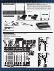
is on.
32. EFFECTS 1 & 2 OUTPUT JACKS
1/4” outputs for external effects. Return stereo
effects into the stereo channels.
33. MONITOR 1-4 XLR OUTPUTS
XLR outputs provide balanced signals for con-
necting either powered monitors or power amps.
34. SUB GROUP 1-4 OUTPUT JACKS
4 balanced 1/4” outputs correspond to the 4 sub
group faders. Depending on the intended use of
the sub groups, connect multi-track recording
devices, powered speakers or power amps.
35. HEADPHONE JACK
1/4” stereo jack for headphone or control room
output.
36. LEFT & RIGHT XLR OUTPUTS
This set of balanced XLR connectors are for
connecting the main L/R output to power amps
or recording gear.
37. MONO/SUB XLR OUTPUTS
A bal. XLR output is featured for side fills or
subwoofers.
1
17
18
34
2
3
5
7
8
9
10
13
14
16
6
32
35
37
24
33
4
6
15
29
27
28
30
31
22
19
26
21
19
11
12
36
21
20
20
23
25
See Demo CARVINCHANNEL.COM