
Owner's Manual

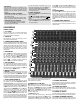


C2440 CONTROLS
CHANNEL FEATURES
1. 1/4” LINE IN
The line connectors are for connecting balanced and
unbalanced instruments, mics and line level sourc e s
such as drum machines or keyboards.
2. XLR MIC IN
The balanced Mic inputs are for connecting pro micro-
phones that use XLR connections.
3. CHANNEL INSERT/CHANNEL DIRECT
To insert a channel effect use a 1/4” TRS (Tip Ring Sleeve)
instrument cable and fully insert it into the jack. Connect
the other end of the cable to the effect’s output. To use as
a direct output for multi-track recording use a 1/4” instru-
ment cable and insert to the first “click” (1/2 insert).
Connect the other end of the cable to an input on a multi-
track recorder.
4. GAIN CONTROL
Adjusts the GAIN when connecting various instruments &
mics. The type of mic (uni-directional, omnidirectional,
etc) and model will require a custom GAIN settings for
each individual mic. Monitor the GAIN level with the PEAK
LED. If an LED is constantly illuminated, decrease the
amount of GAIN. If distortion is present, decrease the
amount of GAIN until the distortion is eliminated.
5. LOW CUT SWITCH
75 Hz low cut filter helps eliminate unwanted low frequen-
cies. Great for reducing “boom” noise from mic stands or
from hollow body acoustic/electric guitars. This filter can
also help “punch up” the bass by turning up the LOW tone
control while using the LOW CUT switch.
6. MID SHIFT SWITCH
The MID SHIFT is an exclusive feature giving you a choice
of two different midrange center frequencies. This is ideal
for vocals and/or instruments. The MID SHIFT is easier to
use than conventional sweep controls because it allows you
to compare for the best vocal or instrument sound by switch-
ng between the two MID frequencies.(2.5k Hz or 700 Hz)
7. ACTIVE 3 BAND CHANNEL EQ
This 4 buss mixer provides studio quality tone controls
with distortion less than .01%–exceptionally clean for
recording & live sound! The ±15 dB boost and cut gives
an overall 30 dB range of powerful EQ control. The active
circuits deliver deep bass from the 20-80 Hz LOW control.
The MID control works in the 2.5k Hz range or the 700 Hz
range depending on the MID SHIFT switch. The HI control
functions at 11-20k for crisper highs. Start out with all
tone controls at their center zero position. Determine
which position your MID SHIFT sounds best at,then cut or
boost your HI, MID and LOW frequencies as needed. If you
are trying to mic instruments such as acoustic guitar or
drums, try various mics and mic placement before adjust-
ing your tone controls (condenser mics work well for these
applications). Cutting and boosting frequencies improper
ly can cause an “un-natural” sound to your vocals or instru-
ments. Your goal is to achieve a natural sound for the
entire performance or recording.
8.CHANNEL AUX 1-2, PRE-POST
AUX 1 & 2 can be used as 2 individual monitor mixes.
Adjust the monitor level from each channel with the AUX 1
& 2 controls. The PRE-POST switch should be set to PRE
(pre-channel EQ and pre-fader) when using AUX 1 & 2 as
monitor mixes. The PRE-POST switch should be set to
POST (post-channel EQ and post-fader) if AUX 1 & 2 is to
be used for effects sends.
9. CHANNEL AUX 3-4, 5-6
Here are 4 more AUX controls paired up. With the 5 - 6
switch OUT the two AUX controls become AUX 3 (the con-
trol labled 3 - 5) and AUX 4 (the control labled 4 - 6 ). When
the 5 - 6 switch is in the IN position, the AUX controls then
become AUX 5 (the control labled 3 - 5) and AUX 6 (the con-
trol labled 4 - 6). This feature gives you a total of 4 auxiliary
mixes and reduces the number of controls that need to be
a d j u s t e d .
10. STEREO PANNING
Each channel’s PA N control allows sweeping stereo effects
when panning from L to R for recordings or live sound.
Superior channel separation is available because of the
“dual element” pan controls providing 15dB greater Left &
Right separation over standard mixers. A true stereo image
can be obtained from any of the output connections marked
L & R.
11. CHANNEL SIGNAL GREEN LED
The signal indicator is pre-fader and post EQ. This LED ver-
ifies that the channel is receiving a signal from the mic or
instrument inputs.
12. CHANNEL PEAK RED LED
This peak indicator is pre-fader and post EQ. A constantly
lit LED indicates the signal probably needs a reduction in
GAIN to prevent input overloading.
13. CHANNEL MUTE SWITCH
Mute a channel instantly without touching your faders.
This is extremely useful when you need to mute channels
but can’t afford to lose fader settings.
14. CHANNEL PFL SWITCH
This switch allows the operator to monitor each channel to
set tone, gain and effect levels before turning up the fader
15. CHANNEL ASSIGNMENT SWITCHES
These switches assign the channels’ signal to the group
faders for sub-mixing and to the Left & Right faders in the
C2440
1
2
3
4
7
10
11
12
13
14
16
5
6
QUICK STA RT UP
If you’re like most new owners, you’re probably in a hurry
to plug your mixer in and use it. Here are some brief
instructions to get you going quickly. With the mixer
unplugged and the unit turned off, complete the following
p r o c e d u r e s :
1. CONNECTING AC POWER TO YOUR MIXER
• The mixer can be used with 120 or 230VAC (it automati-
cally switches internally)
• Use only a grounded (3 prong) outlet to prevent a shock
hazard. This gives the quietest grounding for your mixer.
2. CONNECTING INPUTS TO YOUR MIXER
• For low level balanced devices such as microphones,
plug into the balanced M I C inputs using a shielded
microphone cable with XLR ends.
• For high level balanced or unbalanced devices such as
instruments & Keyboards, plug into the L I N E i n p u t
jacks using a shielded cable with 1/4” Stereo or
standard phone plugs. Adjust the G A I N knob for the mic
or line input being used.
3. TURNING YOUR MIXER ON
• Adjust all channel FADERS and master L E V E L controls to
their
O F F positions
• Adjust all channel H I, M I D, and B A S S controls c e n t e r .
• Adjust all the Channel “PA N ” controls to their c e n t e r
position.
• Turn the mixer on by the rear panel POWER SWITCH a n d
watch for the P O W E R LED to come on. Your mixer is
now ready to operate.
8
9
15