
Owner's Manual


17 2
R16 Resistor, 10K, 1/4W, ±5% 50-10045
R17 Resistor, 10K, 1/4W, ±5% 50-10045
R18 Resistor, 4.70K, 1/4W, ±5% 50-47035
R19 Resistor, 4.70K, 1/4W, ±5% 50-47035
R20 Resistor, 22Ω, 1/2W, ±5% 52-22015
R21 Resistor, 22Ω, 1/2W, ±5% 52-22015
R30 Resistor, 47K, 1/4W, ±5% 50-47045
R31 Resistor, 2.2K, 1/4W, ±5% 50-22035
R32 Resistor, 33K, 1/4W, ±5% 50-33045
R33 Resistor, 27K, 1/4W, ±5% 50-27045
R34 Resistor, 33K, 1/4W, ±5% 50-33045
R35 Resistor, 10K, 1/4W, ±5% 50-10045
R36 Resistor, 10K, 1/4W, ±5% 50-10045
R37 Resistor, 10K, 1/4W, ±5% 50-10045
R38 Resistor, 10K, 1/4W, ±5% 50-10045
R39 Jumper, 0Ω, Carbon, 0 50-00035
R40 Jumper, 0Ω, Carbon, 0 50-00035
R41 Resistor, 150K, 1/4W, ±5% 50-15055
R42 Resistor, 470Ω, 1/4W, ±5% 50-47025
R43 Resistor, 470Ω, 1/4W, ±5% 50-47025
R44 Resistor, 150K, 1/4W, ±5% 50-15055
R45 Resistor, 470Ω, 1/4W, ±5% 50-47025
R46 Resistor, 33K, 1/4W, ±5% 50-33045
R47 N/U
R48 Jumper, 0Ω, Carbon, 0 50-00035
R49 Resistor, 150K, 1/4W, ±5% 50-15055
R50 Resistor, 470Ω, 1/4W, ±5% 50-47025
R51 Resistor, 4.70K, 1/4W, ±5% 50-47035
R52 Resistor, 47K, 1/4W, ±5% 50-47045
R53 Resistor, 100Ω, 1/4W, ±5% 50-10025
R54 Resistor, 150K, 1/4W, ±5% 50-15055
R55 Resistor, 10K, 1/4W, ±5% 50-10045
R60 Resistor, 2.4K, 1/4W, ±5% 50-24035
R61 Resistor, 150K, 1/4W, ±5% 50-15055
R62 Resistor, 2.2K, 1/4W, ±5% 50-22035
R63 Resistor, 220K, 1/4W, ±5% 50-22055
R64 Resistor, 2.2K, 1/4W, ±5% 50-22035
R65 Resistor, 300K, 1/4W, ±5% 50-30055
R66 Resistor, 2.4K, 1/4W, ±5% 50-24035
R67 Resistor, 180K, 1/4W, ±5% 50-18055
R68 Resistor, 2.2K, 1/4W, ±5% 50-22035
R69 Resistor, 360K, 1/4W, ±5% 50-36055
R70 Resistor, 2.0K, 1/4W, ±5% 50-20035
R71 Resistor, 130K, 1/4W, ±5% 50-13055
R72 Resistor, 2.2K, 1/4W, ±5% 50-22035
R73 Resistor, 110K, 1/4W, ±5% 50-11055
R74 Resistor, 2.2K, 1/4W, ±5% 50-22035
R75 Resistor, 110K, 1/4W, ±5% 50-11055
R76 Resistor, 1.8K, 1/4W, ±5% 50-18035
R77 Resistor, 91K, 1/4W, ±5% 50-91045
R78 Resistor, 10K, 1/4W, ±5% 50-10045
R79 Resistor, 150K, 1/4W, ±5% 50-15055
R80 Resistor, 470Ω, 1/4W, ±5% 50-47025
R81 Resistor, 4.70K, 1/4W, ±5% 50-47035
R82 Resistor, 1K, 1/4W, ±5% 50-10035
R83 Resistor, 4.70K, 1/4W, ±5% 50-47035
R90 Resistor, 350Ω, 10W, ±10% 56-35010
R91 Resistor, 350Ω, 10W, ±10% 56-35010
R92 Jumper, 0Ω, Carbon, 0 50-00035
R93 Jumper, 0Ω, Carbon, 0 50-00035
R94 Jumper, 0Ω, Carbon, 0 50-00035
R95 Resistor, 680Ω, 1/4W, ±5% 50-68025
R96 Resistor, 15K, 1/4W, ±5% 50-15045
R97 Resistor, 22K, 1/4W, ±5% 50-22045
R98 Resistor, 22K, 1/4W, ±5% 50-22045
R99 Resistor, 10K, 1/4W, ±5% 50-10045
R100 Resistor, 33K, 1/4W, ±5% 50-33045
R101 Resistor, 680Ω, 1/4W, ±5% 50-68025
R102 Resistor, 15K, 1/4W, ±5% 50-15045
R103 Resistor, 22K, 1/4W, ±5% 50-22045
S1 Switch DPDT Push PC Mtg 25-02201
S4 Switch DPDT Push PC Mtg 25-02201
U1 100V/100W DMOS Audio Amp 60-72940
U2 100V/100W DMOS Audio Amp 60-72940
All “B” Reference Designators are 0 ohm jumpers.
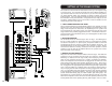
If you’re like most new owners, you’re probably in a hurry to plug your CX mixer
in and use it. Here are some brief instructions to get you going quickly. With the
mixer unplugged and turned off complete the following procedures:
1. CONNECTING AC POWER TO YOUR MIXER
• Check the rear panel to make sure the mixer received uses the proper AC
Line Voltage. (USA 120VAC, Europe 240 VAC ...etc.)
• Use only a grounded (3 prong) power outlet to prevent a shock hazard. This
gives the quietest grounding for your mixer.
2. CONNECTING SPEAKERS
• For connecting speakers, use the two 1/4” speaker jacks on the rear panel.
These jacks are controlled by the main level control on the front panel. The
speaker cables should be non-shielded and at least 18 gauge(AWG) wire.
For speaker cable runs of over 20 feet 16 gauge wire is recommended.
NOTE: Do not run your speakers through microphone cables,
guitar cables, or multi-conductor microphone junction boxes or
“snakes” as they are sometimes referred to. This wire is normal-
ly shielded and of a very light gauge causing a substantial loss of
power and oscillations at high frequencies in the amplifier. All
speaker wires must be non-shielded
.
3. CONNECTING INPUTS TO YOUR MIXER
• For low level balanced devices such as microphones, plug into the balanced
MIC inputs using an XLR shielded microphone cable.
• For high level unbalanced devices such as Tape Recorders and Keyboards
plug into the LINE input jacks using a 1/4” phone shielded cable.
4. TURNING YOUR MIXER ON
• Adjust all channel and master level controls to the off
position
(fully counter clockwise).
• Adjust all “EQ” tone controls, the channel’s Hi, Mid, and Lo and the master 9
Band Graphic EQ, to their center
detent position.
• Turn the mixer on by the rear panel power switch and watch for the power
LED to come on.
Your mixer is now ready to operate.
QUICK START UP
3
2
1
4
6
7
5
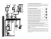
# DESCRIPTION CARVIN # QTY
Switch Cap Grey Extended 07-01603 7
Knob 11 D shaft (COLOR) 07-120-- ---
Front Panel PCB (6 Chan) 80-0630-1 1
POWER TRANSFORMER 15-15070B 1
Accutronics™ REVERB TANK 70-00821
2
SPEAKER JACK PCB 80-0630-3
1
POWER AMP PCB 80-0630-2 1
Yellow
Green
Drk Grey
20
25
28
Color Knob Code
1.
2.
3.
4.
5.
6.
7.
MAINTENANCE
To bring back the new look, your CX mixer can be washed with mild detergent
and/ or a warm damp soft cloth. This will remove normal dust and oil from the
front and back panels. Never spray cleaners or detergents directly at the unit.
The mixer’s are virtually sealed from outside dust and dirt, but it is recommend-
ed to keep the mixer free from dust, dirt, and moisture as much as possible.