
Owner's Manual


3 16
RefDes DESCRIPTION CARVIN #
A1 4558, Dual Low Noise Op Amp 60-45580
A2 4558, Dual Low Noise Op Amp 60-45580
A3 4558, Dual Low Noise Op Amp 60-45580
A4 4558, Dual Low Noise Op Amp 60-45580
A5 4558, Dual Low Noise Op Amp 60-45580
A6 4558, Dual Low Noise Op Amp 60-45580
A7 4558, Dual Low Noise Op Amp 60-45580
A8 4558, Dual Low Noise Op Amp 60-45580
A9 4558, Dual Low Noise Op Amp 60-45580
A10 4558, Dual Low Noise Op Amp 60-45580
A11 4558, Dual Low Noise Op Amp 60-45580
C1 Capacitor, Cera 82pF, 500V 45-82052
C2 Capacitor, Cera 82pF, 500V 45-82052
C3 Capacitor, Elec 10µF, 50V 47-10051
C4 Capacitor, Elec 10µF, 50V 47-10051
C5 Capacitor, Elec 10µF, 50V 47-10051
C6 Capacitor, Elec 10µF, 50V 47-10051
C7 Capacitor, Cera 27pF, 500V 45-27052
C8 Capacitor, Cera 27pF, 500V 45-27052
C9 Capacitor, Elec 10µF, 50V 47-10051
C10 Capacitor, Elec 10µF, 50V 47-10051
C11 Capacitor, Cera 330pF, 1000V 45-33113
C12 Cap, Poly 0.0047µF, 100V 46-47212
C13 Capacitor, Cera 39pF, 500V 45-39052
C14 Capacitor, Elec 47µF, 63V 47-47061
C15 Capacitor, Poly 0.047µF, 100V 46-47312
C16 Capacitor, Poly 0.047µF, 100V 46-47312
C20 Capacitor, Poly 0.1µF, 100V 46-10412
C21 Capacitor, Cera 39pF, 500V 45-39052
C22 Capacitor, Elec 10µF, 50V 47-10051
C23 Capacitor, Cera 39pF, 500V 45-39052
C24 Capacitor, Elec 470µF, 16V 47-47116
C25 Capacitor, Cera 39pF, 500V 45-39052
C26 Capacitor, Elec 10µF, 50V 47-10051
C27 Capacitor, Elec 470µF, 16V 47-47116
C28 Capacitor, Cera 39pF, 500V 45-39052
C29 Capacitor, Elec 10µF, 50V 47-10051
C30 Capacitor, Cera 39pF, 500V 45-39052
C31 Capacitor, Elec 10µF, 50V 47-10051
C32 N/U
C33 Capacitor, Elec 10µF, 50V 47-10051
C34 Capacitor, Poly 0.047µF, 100V 46-47312
C35 Capacitor, Cera 120pF, 500V 45-12152
C40 Capacitor, Elec .47µF, 100V 46-47412
C41 Capacitor, Poly 0.022µF, 100V 46-22312
C42 Capacitor, Poly 0.22µF, 100V 46-22412
C43 Capacitor, Poly 0.01µF, 100V 46-10312
C44 Capacitor, Poly 0.1µF, 100V 46-10412
C45 Capacitor, Poly 0.0047µF, 100V 46-47212
C46 Capacitor, Poly 0.068µF, 100V 46-68312
C47 Capacitor, Poly 0.0033µF, 100V 46-33212
C48 Capacitor, Poly 0.033µF, 100V 46-33312
C49 Capacitor, Poly 0.001µF, 100V 46-10212
C50 Capacitor, Poly 0.022µF, 100V 46-22312
C51 Capacitor, Poly 0.001µF, 100V 46-10212
C52 Capacitor, Poly 0.0068µF, 100V 46-68212
C53 Capacitor, Poly 0.001µF, 100V 46-10212
C54 Capacitor, Poly 0.0047µF, 100V 46-47212
C55 Capacitor, Cera 330pF, 1000V 45-33113
C56 Capacitor, Poly 0.0022µF, 100V 46-22212
C57 Capacitor, Cera 250pF, 500V 45-25152
C58 Capacitor, Cera 56pF, 500V 45-56052
C59 Capacitor, Elec 10µF, 50V 47-10051
C60 Capacitor, Poly 0.047µF, 100V 46-47312
C61 Capacitor, Elec 470µF, 16V 47-47116
C62 Capacitor, Elec 470µF, 25V 47-47125
C63 Capacitor, Elec 470µF, 25V 47-47125
C70 Capacitor, Elec 470µF, 25V 47-47125
C71 Capacitor, Elec 470µF, 25V 47-47125
C72 Capacitor, Elec 4700µF, 50V 42-47251
C73 Capacitor, Elec 4700µF, 50V 42-47251
C76 Capacitor, Elec 10µF, 50V 47-10051
C77 Capacitor, Elec 10µF, 50V 47-10051
C78 Capacitor, Poly 0.1µF, 100V 46-10412
C79 Capacitor, Elec 22µF, 160V 47-22016
C80 Capacitor, Poly 0.1µF, 100V 46-10412
C81 Capacitor, Elec 10µF, 50V 47-10051
C82 Capacitor, Elec 10µF, 50V 47-10051
C83 Capacitor, Elec 10µF, 50V 47-10051
C84 Capacitor, Elec 10µF, 50V 47-10051
C85 Capacitor, Poly 0.1µF, 100V 46-10412
C86 Capacitor, Elec 22µF, 160V 47-22016
C87 Capacitor, Poly 0.1µF, 100V 46-10412
C88 Capr, Mylar 0.047µF, 250VAC 41-47321
D1 LED, Small Red 60-75320
D2 LED, Small Red 60-75320
D3 Diode, 1N4003 0.35” prep. 61-40030
D7 Diode, 1N914 0.35” prep. 61-19140
D10 Diode Rect., MR752 6A 200V 60-75200
D11 Diode Rect., MR752 6A 200V 60-75200
D12 Diode Rect., MR752 6A 200V 60-75200
D13 Diode Rect., MR752 6A 200V 60-75200
F1 Fuse Clips 3AG Vert. PC MTG 23-03529
H1 Conn. Hdr. 8 pin 90° 23-10008
H2 Conn. Hdr 4 pin 90° 23-10014
H3 Conn. Hdr 8 pin 23-10082
J1 XLR Female Neutrik Conn. 21-40000
J2 Jack 1/4”, 3Pin Plastic. 24mm 21-06453
J3 Jack RCA Quad PC Vert. MTG 21-40022
J4 Jack 1/4”, 3Pin Plastic. 24mm 21-06453
J5 Not Assigned
J6 Jack 1/4”, 3Pin Plastic. 24mm 21-06453
J7 Jack 1/4”, 3Pin Plastic. 24mm 21-06453
J8 Jack 1/4”, 3Pin Plastic. 24mm 21-06453
J9 Jack 1/4”, 3Pin Plastic. 24mm 21-06453
J10 Jack 1/4”, 3Pin Plastic. 24mm 21-06453
J11 Jack 1/4”, 3Pin Plastic. 24mm 21-06453
P1 Pot, 12x35mm “D”, B50K-C 71-13057
P2 Pot, 12x35mm “D”, B50K-C 71-13057
P3 Pot, 12x35mm “D”, B50K-C 71-13057
P4 Pot, 12x35mm “D”, B50K 71-13056
P5 Pot, 12x35mm “D”, B50K 71-13056
P6 Pot, 12x35mm “D”, B50K 71-13056
P7 Pot, 12x35mm “D”, B50K 71-13056
P8 Pot, 12x35mm “D”, B50K 71-13056
P9 Pot, 12x35mm “D”, B50K 71-13056
P10 Pot, 12x35mm “D”, B50K 71-13056
P11 Pot, 12x35mm “D”, B50K 71-13056
P20 FADER 50K OHM 71-10332
P21 FADER 50K OHM 71-10332
P22 FADER 50K OHM 71-10332
P23 FADER 50K OHM 71-10332
P24 FADER 50K OHM 71-10332
P25 FADER 50K OHM 71-10332
P26 FADER 50K OHM 71-10332
P27 FADER 50K OHM 71-10332
P28 FADER 50K OHM 71-10332
R1 Resistor, 5.62K, 1/4W, ±1% 50-56231
R2 Resistor, 5.62K, 1/4W, ±1% 50-56231
R3 Resistor, 2.21K, 1/4W, ±1% 50-22131
R4 Resistor, 2.21K, 1/4W, ±1% 50-22131
R5 Resistor, 47K, 1/4W, ±5% 50-47045
R6 Resistor, 10K, 1/4W, ±5% 50-10045
R7 Resistor, 100K, 1/4W, ±5% 50-10055
R8 Resistor, 300K, 1/4W, ±5% 50-30055
R9 Resistor, 100K, 1/4W, ±5% 50-10055
R10 Resistor, 10K, 1/4W, ±5% 50-10045
R11 Resistor, 300K, 1/4W, ±5% 50-30055
R12 Resistor, 2.2K, 1/4W, ±5% 50-22035
R13 Resistor, 100K, 1/4W, ±5% 50-10055
R14 Resistor, 150K, 1/4W, ±5% 50-15055
R15 Resistor, 2.2K, 1/4W, ±5% 50-22035
THIS UNIT CONTAINS HIGH VOLTAGE COM-
PONENTS INSIDE! REFER SERVICING TO
QUALIFIED SERVICE PERSONNEL!
CAUTION
RISK OF ELECTRIC SHOCK
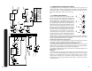
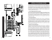
1. LINE INPUT JACK
The 1/4” LINE phone jack is designed for unbalanced line and instrument level
inputs. Examples of these inputs would be instruments such as a guitar, a key-
board, unbalanced mics, or a pre amp output. The line input can be used at
the same time the mic input is being used.
2. XLR MICROPHONE INPUT
The XLR MIC input is designed for balanced low
impedance ( microphone ) input signals. The balance
means the input differential amplifier will reduce the
common noise picked up on the microphone cables.
The XLR connector is wired as per the industry stan-
dard, pin 1 is ground, pin 2 is non-inverting (positive),
and pin 3 is inverting (negative).
Phantom power is available on every XLR input jack
when the phantom power switch, in the master section,
is pressed. This feature allows condenser micro-
phones to be run directly from the mixer.
Note: When using phantom power make sure the
phantom power is switched off before connecting or
disconnecting microphones to the mixer. It is recom-
mended to allow 5 seconds for the phantom power to
discharge before making any microphone connections.
Also to avoid hearing a pop, turn down the main vol-
ume when turning on the phantom power.
3. -20DB PAD SWITCH
This switch reduces the input gain on both the line and
mic input jacks by 20dB. If distortion is heard regardless of the channel LEVEL
control’s setting, engage this switch. This will eliminate the over-driving of the
input amplifier before the channel level control.
4. CHANNEL LEVEL CONTROL
The LEVEL control adjusts the final volume of the channel. Here is where the
individual channel volumes are adjusted to make up the desired mix heard at
the main output. A general rule to prevent distortion with in the mixer, is to
always keep the MAIN master level the same or higher than the channel
LEVEL.
5. MONITOR LEVEL CONTROL
The MONITOR level control adjusts the volume of the channel going to the
monitor mix. Here is where the individual channel monitor volumes are adjusted
to make up the desired mix heard at the monitor output. The monitor level con-
trol is pre channel’s level and tone controls. This means it is unaffected by
adjustments in channel’s level or tone controls. The purpose for this is so the
main mix adjustments for tone and level can be made without disturbing the
monitor mix.
1
MON
LEVEL
MIC
5
4
3
2
1
0 10
9
8
7
6
20
LINE
dB
5
4
3
2
1
0 10
9
8
7
6
1
2
3
4
5
CHANNEL FEATURES CX MONO SERIES PARTS LIST