
Owner's Manual
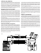


FRONT PANEL
1. PEAK OVERLOAD LED
The red PEAK LED lights any time the signal level at any stage (input/output) comes
within 6db of clipping (distortion). It is okay for the LED to light briefly at musical
peaks, however if it flashes frequently or stays lit, reduce the input gain until this stops.
2. GAIN CONTROL
The GAIN control is used to set up the optimum signal levels between the equal-
izer and any other equipment connected to it. This control allows adjustments
from completely off (fully attenuated) to +6db of gain.
3. FREQUENCY BAND SLIDERS
Each of the EQ2015 & EQ2030’s sliders provide a full 15db of boost or cut on fre-
quency. Many other brands have only a 12db range. Carvin uses long throw slid-
ers for precise adjustments. Each slider features a positive center detent for a true
“flat” setting.
4. EQ BYPASS SWITCH
The EQ2015 and EQ2030 feature a BYPASS switch on each channel allowing you
to compare the equalized signal with the original source. This A/B comparison
lets you measure how effective your settings are in a particular environment.
5. SWEEPABLE LO CUT FILTER
With a range of 10 Hz to 230 Hz, this control can be used as a subsonic filter to
protect power amps from unexpected low end transients such as a dropped micro-
phone, a stage rumble/wind filter, or to reduce 60 cycle hum in environments with
poor AC or ground loops. 35 Hz is a recommended setting.
6. SWEEPABLE HI CUT FILTER
This control has range of 6k to 45kHz. Use it to reduce hiss on recorded tracks
with only low frequency content (such as kick drum or bass guitar), or as an ultra-
sonic filter (20K-up) to protect amps and drivers from damaging oscillations (20k
Hz is the recommended setting when used as an ultra-sonic filter).
REAR PANEL
7. AC POWER CORD & MAIN POWER FUSE
Always use grounded (3 prong) outlets. Defeating the power cord’s ground con-
nection can result in electrocution.
Should the external fuse ever blow, replace only with same type and value:
120 VAC units: 1/4 amp, 5x20mm.
230 VAC units: .125A, 5x20mm.
8. CHANNEL 1 (2) 1/4” PHONE JACK INPUT
This stereo phone jack is designed to receive either balanced or unbalanced input
signals. Balanced signals coming into this jack should be wired with the connector’s
tip going to signal + and the connector’s ring to signal -. The connector’s sleeve
is then tied internally to ground.
9. CHANNEL 1 (2) XLR INPUT CONNECTOR
Like the 1/4” phone jack, this input connector will accept either balanced or unbal-
anced signals. Pin 2 is signal +, pin 3 signal - and pin 1 is grounded.
10. CHANNEL 1 (2) 1/4” PHONE JACK OUTPUT
Like the 1/4” phone input jack, this output connector will accept either balanced
or unbalanced signals. Pin 2 is signal +, pin 3 signal - and pin 1 is grounded.
11. CHANNEL 1 (2) XLR OUTPUT
Like the XLR input jack, this output connector will accept either balanced or unbal-
anced signals. Pin 2 is signal +, pin 3 signal - and pin 1 is grounded.
12. OUTPUT XLR GROUND LIFT SWITCH
This switch defeats the ground on pin 1 of the output XLR connector. Use this
to help eliminate ground loops (AC hum).
21 3 44 55 7
FRONT & REAR PANEL CONTROLS
66
21 34 56
7 129 8 1011
7 129 8 1011