
Owner's Manual
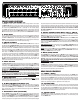

FRONT PANEL FEATURES
1. INPUT LEVELS AND MIXING 1-7
The KB1000 has 7 inputs which are combined to produce a single stereo or mono output.
The INPUT LEVEL control is used to set the input level and how much signal is mixed.
To make sure you have plenty of headroom for mixing, the keyboard output levels should be
set so that turning the INPUT LEVEL to at least “7”, preferably “10” will not cause clipping.
The red CLIP LED indicates when the input is close to clipping. To avoid clipping, reduce the
keyboard level first, then turn down the INPUT LEVEL knob if the clipping persists. The green
SIG LED indicates a signal is present at the input ONLY when the INPUT LEVEL is turned up.
2. INPUT JACKS
Two 1/4” phone jacks are provided on each of the 7 channels to accommodate both stereo and
mono instruments. Plugging mono sources into the “R” jack of an INPUT will send signal to
both LEFT and RIGHT outputs. You can double the amount of inputs by choosing to run in
“MONO” mode and plugging into all 14 (1-7, L&R) input jacks, without regard to stereo assign-
ment. Adjust keyboard output levels to mix L&R inputs accordingly.
3. AMP EQ CONTROLS
The AMP EQ tone controls consist of a LOW, LO MID, HI MID and HIGH controls. These con-
trols DO NOT affect the DIRECT OUT XLRs. Since most of the tone shaping is done within the
keyboard itself, the AMP EQ controls are designed to accomodate for differences in speakers
and acoustic environments. The LOW control affects the lowest frequencies. Excessive “BOOMI-
NESS” can be reduced by turning the LOW control down while turning it up can add fullness
to your sound. The LO MID control adjusts frequencies in the 300Hz range adding extra punch
when needed. The HI MID control adjusts frequencies in the 2.5kHz range allowing you to
“cut through” on a crowded sound stage. The HIGH control knob is designed to cut or boost
the highest frequencies. Usually a “dead” room will will require a boost from the HIGH con-
trol while a “live” room with a lot of reflective surfaces will invite you to reduce the HIGH con-
trol. Note: boosting the high frequencies can result in increased hiss. This is normal. The
AMP EQ is a sound shaping tool which may require some practice to get the best results. Listen
to the results and experiment with different settings.
4. DIRECT OUT XLR
s
The DIRECT OUT XLRs are balanced outputs that get their signal directly from INPUTs 1-7.
These outputs are very useful when connecting to the main mixing board for live performances
or recording. Use the DIRECT OUT LEVEL control to set the output. The MONO switch is used
to combine the LEFT and RIGHT INPUTS so that both L-R DIRECT OUT XLR jacks receive the
same mono signal. NOTE: THE DIRECT OUT MONO SWITCH DOES NOT AFFECT THE STEREO
OR MONO OUTPUT OF THE POWER AMP. A LIFT GND switch is also available on the DIRECT
OUT XLR jacks. Set this switch for the lowest hum/noise when using this output. When the
LIFT GND switch is depressed, the signal ground is lifted from these jacks thus eliminating
any ground loops between the KB1000 and the gear it’s feeding. NOTE: THE AMP EQ, POWER
AMP 1&2 AND MAIN LEVEL CONTROLS DO
NOT AFFECT THE DIRECT OUT SIGNAL.
5. DIRECT OUT LEVEL
The DIRECT OUT LEVEL control sets the output for the DIRECT OUT XLRs ONLY. It will not
affect the volume coming out of the amp speakers or the rear line outs. Communicate with
the mixing engineer to set the proper level.
6. DI MUTE SWITCHES (ON INPUTS 6&7)
Inputs 6 and 7 feature DI MUTE switches. When pressed “IN”, signals from inputs 6 and 7
will be REMOVED from the DIRECT OUT XLRs, but will still be heard through the AMP 1&2
speaker outputs, PHONES jack and rear LINE OUT jacks. This is useful for listening to “click”
tracks, monitor feeds or other sources WITHOUT sending these signals to the DIRECT OUT
XLRs and to the house system.
7. ELECTRONIC X-OVER (BI-AMPING)
When the BI-AMP switch is pressed “IN”, the amp is in the bi-amp mode. This means all fre-
quencies BELOW the X-OVER FREQ are sent to the POWER AMP 1 OUTPUT, while frequen-
cies ABOVE the X-OVER FREQ are sent to the POWER AMP 2 OUTPUT. To select the crossover
frequency, rotate the FREQ control knob until the desired frequency is obtained. Try 800Hz. A
bi-amped system gives the user greater control over the tone. This allows speakers designed
for specific frequencies to be utilized to their fullest potential. Subwoofers will be more effi-
cient at reproducing low frequencies with less distortion. Full range enclosures will not have
to work as hard reproducing the lowest frequencies which consume the most power. Stereo
(L-R) separation from the power amps is no longer possible, but is retained at the DIRECT
OUT XLRs and PHONES jack. NOTE: BI-AMPING DOES NOT NECESSARILY DELIVER THE MOST VOLUME
FROM YOUR SYSTEM.
8. OUTPUT CONTROL GROUP–MAIN, AMP 1L, AMP 2R
The output group controls the volume and amp output levels. The POWER AMP 1 & 2 CON-
TROLS adjust the volume to the individual amps. The MAIN control sets the overall volume.
Try setting the MAIN control to 5 as a starting point.
FULL RANGE MONO (KB1010) AND STEREO: For KB1010 operation push the MONO (MAIN)
switch IN. Turn up the AMP 1L knob on the KB1010 until the desired volume level is reached.
If your are connecting a pair of speakers for stereo use, be sure to release the MONO (MAIN)
switch. Turn up the AMP 1L & AMP 2R knobs until the desired volume level and left and right
balance is reached.
BIAMP CONTROL(combos): To set the balance, bring up the AMP 1L (LOW FREQ) knob until
the desired volume level is reached. Now bring up the AMP 2R (HIGH FREQ) knob until the
desired balance has been achieved.
BRIDGE mode, use only the AMP 1L control, as the AMP 2R control becomes ineffective. If
either of the red PK LEDs flash for AMP1 or AMP2, reduce the POWER AMP 1 or 2 volume
or, engage the LIMITER switch on the rear panel.
9. MONO (MAIN) SWITCH
With the MONO switch in the “OUT” position, the KB1000 will preserve stereo imaging from
the INPUT JACKS to the POWER AMP 1(L) & 2(R) outputs. Setting the MONO switch to the
“IN” position will send the combination of both LEFT and RIGHT signals to both POWER AMP
OUTPUTS. Helpful if only one speaker cabinet is used, or if stereo imaging is not important.
NOTE: THE
MONO (MAIN) SWITCH DOES NOT AFFECT THE STEREO OR MONO OUTPUT OF
XLR DIRECT OUTS.
10. PHONES JACK
A PHONES jack is provided for practicing or monitoring. The MAIN knob controls the volume.
The phones jack does not interrupt the amplifier output. To listen to the PHONES output with-
out sound from the speakers, turn down the POWER AMP 1&2 controls. A high-current head-
phone amp drives this output for any pair of headphones.
REAR PANEL FEATURES
11. POWER / (RESET)
Push the upper portion of the POWER SWITCH to turn the amplifier on. If the POWER LED is
on but no sound is coming out of the speakers, the amp may have gone into one of its pro-
tection modes with the PROTECT LED ON. To reset the amp, turn the power off for one minute
and then turn the amp back on. If the problem persists, check for; a) The speaker impedance
is too low for the bridge output (4 ohm min.) or normal outputs (2 ohms min. per amp) b) bad
speaker cable, c) damaged speaker or d) blocked rear fan cooling vents.
12. COOLING VENTS
The rear vents cool the internal power amps. Provide a minimum of 3” clearance for adequate
ventilation. Blocking the air flow to these vents will cause the amp to thermally protect and
turn the speaker relays off. The PROTECT LED on the front panel will light. If this happens,
clear the obstruction first, keep the power on, allowing the amp to cool. The amp will engage
the speaker relays when cooling conditions return to normal.
13. LIMITER SWITCH
The KB1000 features distortion-free, optoislator power amp limiters. Limiters help prevent
power amp clipping by reducing peaks before they reach the amp. To use this feature, press
“IN” the LIMITER switch.
6
4
5
8
9
1
2
7
3
10
11