
Owner's Manual

19. REVERB CONTROL / REVERB ON SWITCH / LED
Set the REVERB control for the overall amount of Reverb available. Then for
each channel 1-3, press the REVERB SWITCH to select which channels you
want the Reverb working. The “ON” LED will show Reverb is active for the chan-
nel you are currently using. When you come back to that channel, the amp will
remeber if the Reverb should be On or Off. The REVERB circuits are located
after the EFFECT LOOP and before the MASTER. The REVERB can also be
turned on/off through the rear REVERB footswitch 1/4” jack, or by MIDI control.
20. STANDBY SWITCH
Use the STANDBY SWITCH If you are taking a break. This turns the high volt-
age off, increasing the life of your power tubes while keeping the power and pre-
amp tube filaments on for immediate use.
21. POWER SWITCH & INDICATOR
The power switch is to be utilized as the master ON/OFF switch. As the amp is
turned on, the RED portion of the power switch will illuminate as your ON indica-
tor.
REAR PANEL
22. SPEAKER JACKS
Two 1/4” SPEAKER JACKS are featured to operate several speaker systems
at the same time. Calculate the total speaker impedance based on parallel wiring
as both speaker jacks are wired in parallel. Select the IMPEDANCE SWITCH for
the correct impedance.
23. SPEAKER IMPEDANCE SWITCH
The SPEAKER OHMS switch offers the selection of 4, 8 or 16 ohms () to
match your speaker systems. The correct setting for one C412 cabinet is 16.
For use with two C412 (16 ohm) cabinets, the correct setting would be 8. In the
case of connecting two 8 ohm systems such as the C212E 8 ohm extension cab-
inet, move the switch to 4 ohms.
24. RMS POWER SWITCH
The 3-position RMS POWER switch reduces the 100 watt output of the amp
down to 50 or 15 watts, while still using all four output tubes. Lower settings will
allow the great sound and feel of the tube power amp being overdriven, but at
lower volume levels.
For maximum output power and headroom set the
switch to 100 watts
.
For early power amp saturation move this switch to 50
or 15 watts. The maximum volume reduction will only be 3dB and 8dB respec-
tively.
25. POWER TUBE BIAS SWITCH
If you desire to change from EL34 to 5881 (6L6GC) power tubes, you may do
so by selecting the external BIAS switch to the 5881 (6L6GC) position on the rear
panel. Be sure that this switch is selected to the proper position or excessive heat
will damage your tubes.
We recommend re-biasing when changing power tubes. The internal P11 bias
trim control can be set by a qualified technician. To set the bias, measure the cur-
rent across the terminals of the STANDBY switch (set this switch to the off posi-
tion when the amp is on). Set the idle current to 100 mA for all tube types.
26. VOICED LINE OUT
The LINE OUT 1/4” jack is “CABINET VOICED” to prevent excessive bass or
highs going to your mixer. This greatly aids in sound quality because you do not
have to move your mixer EQ settings to the extreme. The 1.5 VAC output (refer-
ence to 100 watts output at 8 ohms) is more than adequate to drive any profes-
sional mixer or power amp.
27. FS44M FOOTSWITCH JACK (NOT a MIDI JACK)
Connect only the Carvin FS44M to this jack. Other devices will not work and
may cause damage. The FS44M will allow you to remotely choose channel 1, 2
or 3 and activate the master BOOST function. The LEDs on the FS44M indicate
your selections, and will also reflect changes made through the MIDI IN jack.
28. REVERB FOOTSWITCH JACK (FS22)
The front panel REVERB on/off feature will follow (track) your channel selection
or MIDI, however you may want to switch it manually with a footswitch.
Connecting an FS22 will allow you to toggle the REVERB on/off.
Other basic footswitches with a 1/4” plug will work.
29. MIDI IN / MIDI THRU
Connect any standard MIDI controller to the MIDI IN jack with a 5-pin MIDI
cable. You can connect other MIDI compatible devices to the MIDI THRU.
(See MIDI PROGRAMMING at the end of this page.)
30. EFFECTS LOOP: SEND and RETURN
For the lowest possible noise from an effects processor, use the EFFECT LOOP
SEND and RETURN. To use the EFFECTS LOOP, plug the INPUT of your effects
into the SEND jack and the OUTPUT of your effects into the RETURN jack. Use
shielded cables, not speaker cables. It’s possible to have a slight gain reduction of
a few dB with some effects units. However, the amp has plenty of gain to over-
come any loss. The SEND jack levels will not be affected by the MASTER control.
31. MASTER OUT and POWER AMP IN
The MASTER control affects the MASTER OUT jack level to
allow control of mul-
tiple amps from a single knob
. Signals sent into the POWER AMP IN feed direct-
ly to the power amp section and will have no volume control. These jacks can also
be used as an effects loop, however if you are using dynamics based effects that
rely on very specific signal level settings (compressor, auto-wah) it is recommend-
ed to use the EFFECTS LOOP instead.
32. AC POWER & FUSE
First, make sure the AC VOLTAGE switch is set for the voltage in your area.
The detachable AC POWER CORD supplied is designed to operate with one
type of voltage (for European 230VAC use a CEE-7 plug cord set). Make sure
the cord is securely inserted into the back of the unit. Plug the cord into a ground-
ed “3 prong” power source. No attempt should ever be made to defeat or use the
amp without the ground connected. The fuse is located inside the AC jack.
33. AC VOLTAGE SELECTOR
BEFORE you insert the AC cord into it’s receptacle, make sure the AC voltage
switch is set for your region (120VAC in the USA), and remove the warning label.
The wrong setting may cause severe damage to your amp and will not be cov-
ered by the warranty.
For the 240VAC setting, replace the fuse with a 3A fuse before operating.
34. LED SET BUTTON
The Legacy 3 has internal LED lighting that can be set to change color with
channel selection, by MIDI presets, or by CC control.
To change the LED backlighting color:
1. Press and hold down the channel switch you want to change the color for.
(1, 2 or 3)
2. While still holding the first switch in, press in the other two switches, then
release all switches at once.
3. On the back panel, press and release the "SET LED" button to set the
lighting color to GREEN, RED, AMBER or OFF.
4. Press and release any channel (1,2,3) button to save and exit. Normal
operation is resumed.
- SEE NEXT PAGE FOR MIDI SETTINGS -
GETTING STARTED QUICKLY
If you are like most players, you probably want to plug in your new amp and get
started playing it right away. You can read the rest of the manual later to learn the
finer points of operating your amp. In order to get started you will need your
Legacy 3 amp, a 120 or 230 AC grounded power outlet, your instrument, a stan-
dard guitar cord, a speaker cabinet and speaker cable.
First, make sure the rear 120VAC/240VAC switch is set for the voltage in your
area. With the amp turned off, plug it into the proper AC voltage.
Then, set the rear panel Speaker Ohms switch to match the speaker cabinet(s)
you are using. (If two of the same cabinets are used, set the switch for 1/2 value.)
Turn all the volume and drive controls off and set tone controls to their center
position. If you have purchased the FS44M footswitch, plug it into the rear foot
switch jack for switching the channels 1, 2, 3 and Boost.
Now, turn ON the Power switch, wait 5-10 seconds, then turn ON the Standby
switch. Allow 30 seconds for the tubes to warm up. Turn up the Master slightly,
and gradually raise the Channel Volumes and Drives. Adjust the tone controls
and you’re ready to go.
If you experience problems with the amp, first check all connections and set-
tings. If you still feel your amp is malfunctioning, contact Carvin. Occasionally
tubes are damaged in shipping.
FRONT PANEL
1. GUITAR INPUT
A standard 1/4” input jack feeds all channels through using the SELECT switch.
Use a professional quality guitar cord no longer than 25 feet. Typical cable
capacitance should be under 50pf—the longer the cord, the greater the capaci-
tance (you can measure this with a capacitance meter). A long cable with high
capacitance will reduce the overall treble response from your guitar pickups.
2. CHANNEL SELECT SWITCHES
Choose the desired channel with switch 1, 2, or 3. The LED’s next to the vol-
ume controls will let you see which channel is functioning, and will also be dis-
played on the external FS44M footswitch LED’s. Use channel 1 for pristine clean
playing without breakup. Use channels 2 & 3 for thicker rhythm or overdriven
lead sounds and use the GAIN switch on channel 3 for super high gain lead
sounds. Channel changes can also be made with the FS44M footswitch or by
MIDI control.
Pressed in combination, these switches allow access to various MIDI settings.
CLEAN CHANNEL 1
Channel 1 gives you crisp, clean playing with high headroom and no breakup.
Thanks to special mud-cutting circuits that work between the frequencies of 500
and 700 Hz, your guitar tones will be full and vibrant.
3. CLEAN CHANNEL INDICATOR
The green LED will indicate the CLEAN channel is selected.
4. CLEAN VOLUME
This control sets the CLEAN channel 1 volume
.
The MASTER control also
affects output.
5. 6. 7. CLEAN—BASS, MID & TREBLE CONTROLS
You can start at 5 on the dial for each of the tone controls. However, these set-
tings do not represent a normalized (flat) sound. You need to set them where
they sound best! Most musicians like to reduce the MID’S between 1 and 4 for
deeper bass and crisper highs. If your sound is too bright with single coil pick-
ups, you may want to keep the PRESENCE switch off
.
8. CLEAN PRESENCE
For added clarity, the PRESENCE switch increases only the highest guitar har-
monics in the 8-10k Hz range which is ideal for brightening up dual coil neck pick-
ups
.
LEAD CHANNELS 2 & 3
9. LEAD CHANNEL INDICATORS for CH.2 & CH.3
The red LED will indicate LEAD channel 2 is selected.
The yellow LED(s) will indicate LEAD channel 3 is selected.
10. 11. 12. LEAD BASS, MID & TREBLE
To start off with, set the BASS, MID & TREBLE controls at their center (5) posi-
tion. These controls are set according to the sound you are looking for. Once you
have the sound you like, you can set the seperate CH2 and CH3 PRESENCE
and DRIVE controls for CH2 and CH3 to get different sounds between channels.
Even though you may have found “your sound”, you may want to change the set-
tings for different guitars or playing conditions. It’s normal to decrease the BASS
at higher playing levels, or adjust the TREBLE or PRESENCE for different
rooms.
13. LEAD PRESENCE - CH.2 & CH.3
Channels 2 & 3 feature seperate PRESENCE controls. The wide range of these
controls, in the higher range of the tonal spectrum, can be set for very different
sounds from each channel. Turning the PRESENCE “up” can allow one channel
to stand out in the mix, or sound more agressive. Turning PRESENCE “down”
can produce a smoother, thicker sound. Adjust each DRIVE, VOLUME, and the
Channel 3 GAIN switch for even more variety.
14. DRIVE - CH.2 & CH.3 ***
For mild tube saturation, set the DRIVE control between 1 & 2. For some of the
best rhythm sounds, set the drive control set between 3 & 6. For full blown over-
drive, set the control between 7 and 10. With high-output pickups, Drive settings
above 8 can be subject to over saturation causing sluggish distortion. If so, play
your guitar with it’s volume at 10 and decrease the DRIVE until the crisp highs
come back. For very high gain playing, try Channel 3 with the GAIN switch.
*** USING THE VAI “HIDDEN FEATURE”
One of the “hidden” features of the Legacy series amplifiers is using a technique
that Steve Vai requested be part of the amp for his own use. While playing on the
lead channel with a generous amount of DRIVE (around 6), back off the volume
on your guitar. You will find the channel actually “cleaned up” with your guitar at
a lower volume. This is a great feature for playing both rhythm and lead without
switching channels. You will also find that the amp will be very responsive to your
“attack”. An advanced player knows how to vary their attack when picking or
strumming, and the Legacy 3 is designed to respond to this.
15. CHANNEL 3 GAIN SWITCH and LED
Channel 3 has a GAIN switch for adding even more drive to the classic Legacy
sound, while still retaining 12AX7A tube dynamics. Super-hi-gain sounds are
available without the need for external pedals that can limit dynamics.
The yellow LED near the GAIN switch will indicate the GAIN is ON for CH.3.
16. LEAD VOLUMES
Set the volumes of the LEAD channel 2 or 3 with these controls.
The MASTER
control also affects output
.
MASTER SECTION
17. MASTER
Set the MASTER control for overall volume of the amp.
The MASTER affects
the MASTER OUT jack level to
allow control of multiple amps from a single knob.
The MASTER will not affect the Effect Loop Send level
.
18. BOOST / LED
The BOOST control allows you to add an overall volume increase to the amp
by up to +6dB, whenever you may need it. The BOOST can be activated through
the remote FS44M footswitch, or by MIDI control.
The BOOST does not affect the
SEND jack, only the MASTER OUT jack
.
LEGACY 3 - VL300
Select proper AC VOLTAGE.
Press firmly to fully insert cord.
2
32 33
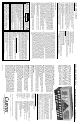
REAR PANEL FEATURESFRONT PANEL FEATURES
191817 15 13 14 16 9
191614131011124 3856721
20
30
2625242322
292834 27
31