4-244-183-71(1) Home Theater System Operating Instructions Owner’s Record The model and serial numbers are located at the rear of the unit. Record the serial number in the space provided below. Refer to them whenever you call upon your Sony dealer regarding this product. Model No. Serial No.
WARNING To prevent fire or shock hazard, do not expose the unit to rain or moisture. To prevent fire, do not cover the ventilation of the apparatus with newspapers, table-cloths, curtains, etc. And don’t place lighted candles on the apparatus. To prevent fire or shock hazard, do not place objects filled with liquids, such as vases, on the apparatus. Don’t throw away the battery with general house waste, dispose of it correctly as chemical waste.
Table of Contents List of Button Locations and Reference Pages Main unit ............................................... 5 Hooking Up the Components Required cords ....................................... 6 Antenna hookups ................................... 7 Audio component hookups .................... 8 DVD Player/Video Cassette Recorder hookups ........................................... 9 Video component hookups .................. 10 Digital component hookups ................. 11 Other hookups ........
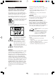
About This Manual Note for the supplied remote For RM-PP65 The HT-DDW650 consists of: – Receiver – Speaker system • Front/surround speakers • Center speaker • Sub woofer STR-K650P The >10/11 and 12 buttons on the remote are not available. SS-MSP75 SS-CNP75 SA-WMSP85 Tip The instructions in this manual describe the controls on the receiver. You can also use the controls on the supplied remote if they have the same or similar names as those on the receiver.
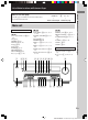
List of Button Locations and Reference Pages Illustration number Use this page to find the location of buttons that are mentioned in the text. DISPLAY 2 (22, 42) R R Name of button/part Reference page Main unit M–O ALPHABETICAL ORDER A–L A.F.D.
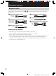
Hooking Up the Components Required cords The following optional connection cords A – E are required when you hook up the components (pages 8 – 11).
Antenna hookups FM wire antenna (supplied) DIGITAL ANTENNA OPTICAL VIDEO 2 IN MONITOR AM y VIDEO IN VIDEO IN VIDEO OUT VIDEO IN VIDEO OUT FM 75Ω COAXIAL DVD IN Hooking Up the Components AM loop antenna (supplied) COAXIAL L AUDIO OUT R IN CD IN OUT MD/TAPE AUDIO IN AUDIO IN AUDIO OUT AUDIO IN DVD VIDEO 2 VIDEO 1 SUB WOOFER * * The shape of the connector varies depending on the area code.
Audio component hookups MD or Tape deck INPUT OUTPUT LINE LINE L A A ç R ç OUT DIGITAL IN ANTENNA OPTICAL VIDEO 2 IN MONITOR AM y VIDEO IN VIDEO IN VIDEO OUT VIDEO IN VIDEO OUT FM 75Ω COAXIAL DVD IN COAXIAL L AUDIO OUT R IN OUT IN MD/TAPE CD AUDIO IN AUDIO IN AUDIO OUT AUDIO IN DVD VIDEO 2 VIDEO 1 SUB WOOFER A OUTPUT LINE L R CD player 8US HT-DDW650 4-244-183-71(1) US
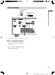
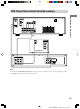
DVD Player/Video Cassette Recorder hookups MONITOR AM y VIDEO IN VIDEO IN VIDEO OUT VIDEO IN VIDEO OUT E FM 75Ω COAXIAL DVD IN R COAXIAL L L R L AUDIO OUT R IN CD OUT IN MD/TAPE AUDIO IN AUDIO IN AUDIO OUT AUDIO IN DVD VIDEO 2 VIDEO 1 R SUB WOOFER L R FRONT CENTER SPEAKERS L SURROUND IMPEDANCE USE 8 – 16Ω A INPUT VIDEO IN Hooking Up the Components ANTENNA DIGITAL OPTICAL VIDEO 2 IN COMPONENT VIDEO IN Y Pb Pr TV Monitor C F DVD & VCR IN (FROM ANT.
Video component hookups If you are not going to hookup a DVD Player/Video Cassette Recorder, you can hookup your video components as shown below.
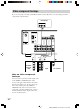
Digital component hookups Connect the digital output jacks of your DVD player and satellite tuner (etc.) to the receiver’s digital input jacks to bring the multi channel surround sound of a movie theater into your home. To fully enjoy multi channel surround sound, five speakers (two front speakers, two surround speakers, and a center speaker) and a sub woofer are required. Note All the OPTICAL and COAXIAL jacks are compatible with 96 kHz, 48 kHz, 44.1 kHz and 32 kHz sampling frequencies.
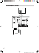
Other hookups AC power cord b To a wall outlet R L R R L FRONT SPEAKERS R CENTER L L SURROUND IMPEDANCE USE 8 – 16Ω Connecting the AC power cord Before connecting the AC power cord of this receiver to a wall outlet, connect the speaker system to the receiver (page 13). Connect the AC power cord(s) of your audio/ video components to a wall outlet.
Hooking Up and Setting Up the Speaker System Speaker system hookups Required cords A Speaker cords (supplied) B Monaural audio cord (supplied) (+) Hooking Up and Setting Up the Speaker System Black (–) Active sub woofer Front speaker (R) Front speaker (L) INPUT AUDIO IN E e B b e E A A To a wall outlet (Switch the power (POWER) to off before connecting the power cord.
Speaker system hookups (continued) Examples of poor conditions of the speaker cord Tip To prevent speaker vibration or movement while listening, attach the supplied foot pads at the bottom of the speakers. Stripped speaker cord is touching another speaker terminal. Notes • Connect the long speaker connecting cords to the surround speaker terminals and the short speaker connecting cords to the front and center speaker terminals. • Twist the stripped ends of the speaker cords about 2/3 inch.
Performing initial setup operations Make sure that you turn down the volume before you turn off the receiver. When you turn on the receiver, the volume remains at the level you turn off the receiver. Before using your receiver for the first time, adjust SET UP parameters so that the receiver correspond to your system. For the adjustable parameters, see the table on page 46. See pages 15–19 for speaker settings and page 33 for other settings.
Multi channel surround setup (continued) When placing surround speakers behind you (wide room) B Sub woofer A A If you change the speaker system, select “NORM. SP.”. You can adjust the speaker size and sub woofer selection when you select “NORM. SP.” (page 18). To select “NORM. SP.”, turn off the power, then turn on again while pressing MAIN MENU. (To reset to “MICRO SP.”, do the same procedure.) 45° Tip C The setting for Micro Satellite Speaker (MICRO SP.
x Front speaker distance ( XX ft.) L R DIST. Set the distance from your listening position to the front speakers (A on page 15). C DIST. Set the distance from your listening position to the center speaker. Center speaker distance should be set from a distance equal to the front speaker distance (A on page 15) to a distance 5 feet closer to your listening position (B on page 15). x Surround speaker distance ( DIST. XX ft.) SL SR Set the distance from your listening position to the surround speakers.
Multi channel surround setup (continued) Tip The surround speaker placement parameter is designed specifically for implementation of the Digital Cinema Sound modes with virtual elements. With the Digital Cinema Sound modes, speaker placement is not as critical as other modes.
x Surround speaker size ( SL SR XXXXX) • If you connect large speakers that will effectively reproduce bass frequencies, select “LARGE”. Normally, select “LARGE”. However, if the front speakers are set to “SMALL”, you cannot set the surround speakers to “LARGE”.
Multi channel surround setup (continued) Checking the connections Listening to the sub woofer POWER indicator POWER After connecting all of your components to the receiver, do the following to verify that the connections were made correctly. 1 Press ?/1 to turn on the receiver. 2 Turn on the component that you connected (e.g., CD player or tape deck). First, turn down the volume on the receiver. The volume should be set to minimum before you begin playing the program source.
Basic Operations Selecting the component Input Selector buttons Select To OPT IN Specify the digital audio signals input to the DIGITAL OPTICAL input jacks. ANALOG Specify the analog audio signals input to the AUDIO IN (L/R) jacks. Press the input selector button to select the component you want to use.
Changing the display DIMMER Press DIMMER repeatedly to adjust the brightness of the display (3 steps). However, when you press any button, the display becomes the brightest setting temporary.
Enjoying Surround Sound You can take advantage of surround sound simply by selecting one of the receiver’s preprogrammed sound fields. They bring the exciting and powerful sound of movie theaters and concert halls into your home. You can also customize the sound fields to obtain the sound you want by changing the surround parameter. To fully enjoy surround sound, you must register the number and location of your speakers.
Enjoying higher fidelity sound (continued) Enjoying stereo sound in multi channel (Dolby Pro Logic ) This receiver incorporates with Dolby Pro Logic II which has movie mode and music mode, and the receiver can reproduce the 2 channel sound in 5.1 channel through Dolby Pro Logic II. Press A.F.D. repeatedly to select “DOLBY PL”, “PL MOV” or “PL MUS”. The A.F.D. indicator lights up and the selected type of decoding is indicated in the display.
x C.ST.EX A (Cinema Studio EX A) Reproduces the sound characteristics of the Sony Pictures Entertainment “Cary Grant Theater” cinema production studio. This is a standard mode, great for watching most any type of movie. Selecting other sound fields Press MUSIC repeatedly to select the sound field you want. The MUSIC indicator lights up and the current sound field is indicated in the display. x C.ST.
Understanding the multi channel surround displays 1 2 3 SP L SW SL qs C R aDIGITAL OPT COAX 4 5 6 a PRO LOGIC II DTS D.RANGE STEREO MONO MEMORY SLEEP LFE S SR q; 9 8 7 qa 1 SW: Lights up when sub woofer selection is set to “YES” (page 18) and the audio signal is output from the SUB WOOFER jacks. 6 Tuner indicators: Lights up when using the receiver to tune in radio stations, etc. See pages 29 – 31 for tuner operations. 2 SP: Lights up when you turn on the receiver.
qs Playback channel indicators: The letters (L, C, R, etc.) indicate the channels being played back. The boxes around the letters vary to show how the receiver downmixes the source sound (based on the speakers settings). When using sound fields like “C.ST.EX”, the receiver adds reverberation based on the source sound. L (Front Left), R (Front Right), C (Center (monaural)), SL (Surround Left), SR (Surround Right), S (Surround (monaural or the surround components obtained by Pro Logic processing)).
Customizing sound fields (continued) Adjusting the tone parameters Front balance ( The TONE menu contains parameters that lets you adjust the tone of the front speakers for optimum sound. The settings are applied to all sound fields. L R BAL. L/R XX) Lets you adjust the balance between front left and right speakers. Center level (CTR XXX dB) Lets you adjust the level of the center speaker. Surround left level (SUR.L.
Receiving Broadcasts 4 If you’ve tuned in an AM station, adjust Before receiving broadcasts, make sure you have connected FM and AM antennas to the receiver (page 7). the direction of the AM loop antenna for optimum reception. 5 Repeat steps 1 to 4 to receive another station. Direct tuning You can enter a frequency of the station you want directly by using the numeric buttons on the supplied remote. For details on the buttons used in this section, see pages 35–39.
Automatic tuning If you don’t know the frequency of the station you want, you can let the receiver scan all available stations in your area. 1 Press TUNER FM/AM repeatedly to select the FM or AM band. The last received station is tuned in. 2 Press TUNING + or TUNING –. Press TUNING + to scan from low to high; press TUNING – to scan from high to low. The receiver stops scanning whenever a station is received. When the receiver reaches either end of the band Scanning is repeated in the same direction.
Tuning to preset stations You can tune the preset stations by either of the following two ways. Scanning the preset stations 1 Press TUNER FM/AM. The last received station is tuned in. 2 Press PRESET TUNING + or PRESET TUNING – repeatedly to select the preset station you want. Each time you press the button, the receiver tunes in one preset station at a time, in the corresponding order and direction as follows: nC0˜...
Other Operations 4 Press ENTER. 5 Repeat steps 2 to 4 to assign index Naming preset stations and program sources name for another station or program source. You can enter a name (index name) of up to 8 characters for preset stations and program sources. These names (for example, “VHS”) appear in the receiver’s display when a station or program source is selected. Note that no more than one name can be entered for each preset station or program source.
Recording on a video tape You can record from a VCR, a TV or a DVD player using the receiver. You can also add audio from a variety of audio sources when editing a video tape. See the operating instructions of your VCR or DVD player if you need help. 1 Select the program source to be recorded. 2 Prepare the component for playing. For example, insert the DVD you want to record into the DVD player. 3 Insert a blank video tape into the VCR (VIDEO 1) for recording.
Changing the command mode of the receiver This function is useful when you use 2 Sony receivers in the same room. 1 Turn off the receiver. 2 Hold down ENTER and press 1/u to turn on the receiver. “C.MODE.AVX” appears in the display. Each time you repeat the procedure above, the display changes as follows: C.MODE.AV1 y C.MODE.AV2 Tip The initial setting is “C.MODE.AV2”. Notes • The command mode of the supplied remote is “AV2” and you cannot change this setting.
Operations Using the Remote RM-PP65 You can use the remote RM-PP65 to operate the components in your system. You can also use this remote to operate the DVD PLAYER/ VIDEO CASSETTE RECORDER (SLV-D300P). Remote button description TV ?/1 Before you use your remote ?/1 AV ?/1 SELECT SYSTEM STANDBY DVD VIDEO1 CD TUNER 2CH A.F.D. ANT MODE T.TONE 2 3 VIDEO2 MD/TAPE AUDIO 1 Inserting batteries into the remote PRESET/ CH/D.
Remote Button Description (continued) Remote Button Operations Function CD Receiver To listen to compact disc. TUNER Receiver To listen to radio programs. 2CH Receiver Selects 2CH ST. mode. A.F.D. Receiver Selects A.F.D. AUTO, DOLBY PL, PLII MOV and PLII MUS. MODE Receiver Remote Button Operations SYSTEM STANDBY (Press AV ?/1 and ?/1 at the same time) Receiver/ Turns off the receiver TV/ and other Sony audio/ Satellite tuner/ video components.
Remote Button Operations Function Remote Button Operations ENTER TV/ DVD PLAYER/ VIDEO CASSETTE RECORDER (VIDEO mode)/ Satellite tuner/ MD deck/ Tape deck After selecting a channel, disc or track using the numeric buttons, press to enter the value. x CD player/ DVD PLAYER/ VIDEO CASSETTE RECORDER/ MD deck/ Tape deck DVD PLAYER/ VIDEO CASSETTE RECORDER (VIDEO mode) Selects output signal from aerial terminal: TV signal or VCR program. ANT Skips tracks.
Remote Button Description (continued) Remote Button Operations Function O DVD PLAYER/ Returns to the previous VIDEO menu or exits the menu. CASSETTE RECORDER (DVD mode) V/v/B/b Satellite tuner/ Selects a menu item. DVD PLAYER/ VIDEO CASSETTE RECORDER ENTER/ EXECUTE Satellite tuner/ Press to enter the DVD PLAYER/ selection.
To reset a button to its factory setting TV Maker SONY 01 Repeat the above procedure. AKAI 04 To reset all the input selector buttons to their factory setting AOC 04 CENTURION 12 Press ?/1, AV ?/1 and MASTER VOL – at the same time. CORONADO 03 CURTIS-MATHES 12 Controlling other TVs with the remote commander Code(s) DAYTRON 12 EMERSON 03, 04, 14 FISHER 11 The remote commander is pre-programmed to control non-Sony TVs.
Additional Information Precautions On safety Should any solid object or liquid fall into the cabinet, unplug the receiver and have it checked by qualified personnel before operating it any further. On power sources • Before operating the unit, check that the operating voltage is identical with your local power supply. The operating voltage is indicated on the nameplate at the rear of the receiver.
There is no sound from a specific component. • Check that the component is connected correctly to the audio input jacks for that component. • Check that the cord(s) used for the connection is (are) fully inserted into the jacks on both the receiver and the component. • Check that you have selected the correct component on the receiver. There is no sound from one of the front speakers. Connect a pair of headphones to the PHONES jack to verify that sound is output from the headphones (page 21).
Troubleshooting (continued) The FM reception is poor. Use a 75-ohm coaxial cable (not supplied) to connect the receiver to an outdoor FM antenna as shown below. If you connect the receiver to an outdoor antenna, ground it against lightning. To prevent a gas explosion, do not connect the ground wire to a gas pipe. Receiver Outdoor FM antenna ANTENNA AM y FM 75Ω COAXIAL Ground wire (not supplied) To ground Radio stations cannot be tuned in. • Check that the antennas are connected securely.
Specifications Inputs (Digital) DVD (Coaxial) Sensitivity: – Impedance: 75 ohms S/N: 100 dB (A, 20 kHz LPF) AUDIO POWER SPECIFICATIONS POWER OUTPUT AND TOTAL HARMONIC DISTORTION: With 8 ohm loads, both channels driven, from 40 – 20,000 Hz; rated 70 watts per channel minimum RMS power, with no more than 0.7 % total harmonic distortion from 250 milliwatts to rated output. Amplifier section Reference Power Output (8 ohms 1 kHz, THD 0.
Specifications (continued) Speaker section AM tuner section SS-MSP75 for front and surround speakers SS-CNP75 for center speaker Speaker system Full range, magnetically shielded Tuning range With 10-kHz tuning scale: 530 – 1710 kHz4) With 9-kHz tuning scale: 531 – 1710 kHz4) Antenna 70 mm × 100 mm cone type Enclosure type Bass reflex Rated Impedance 8 ohms Loop antenna Intermediate Frequency 450 kHz Usable sensitivity 50 dB/m (at 1,000 kHz or 999 kHz) S/N 54 dB (at 50 mV/m) Harmonic distortio
Continuous RMS power output (6 ohms, 20 – 250 Hz) 100 W Reproduction frequency range 28 Hz – 200 Hz High frequency cut-off frequency 150 Hz Input LINE IN (input pin jacks) Power requirements 120 V AC, 60 Hz Power consumption 100 W Dimensions (w/h/d) Approx. 10 3/4 × 12 7/8 × 15 3/4 inches including front panel Mass 22 lb 1 oz For details on the area code of the component you are using, see page 4.
Tables of settings using the MAIN MENU button You can make various settings using the MAIN MENU, MENU / tables below show each of the settings that these buttons can make. Press MAIN MENU repeatedly to select LEVEL Press MENU to select L R or MENU BAL. L/R XX CTR XXX dB L +8 to R +8 (1 steps) 27 –10 dB to +10 dB (1 dB steps) –10 dB to +10 dB (1 dB steps) –10 dB to +10 dB (1 dB steps) S.W. XXX dB –10 dB to +10 dB (1 dB steps) SW L C SL L C 1) Page SUR.R. XXX dB COMP. XXX EFCT.
Adjustable parameters for each sound field The adjusted BASS and TREB. parameters are applied to all sound fields. < TONE > BASS TREB. 2CH ST. z z A.F.D. AUTO z z DOLBY PL z z PLII MOV z z PLII MUS z z C.ST.EX A z z C.ST.EX B z z C.ST.EX C z z HALL z z JAZZ z z CONCERT z z PCM 96K The adjusted LEVEL parameters are applied to all the sound fields except for EFCT. parameter. For EFCT. parameter, the settings are stored individually for each sound field.
US Sony Corporation Printed in Malaysia HT-DDW650 4-244-183-71(1) US