HP ProLiant DL60 Gen9 Server Maintenance and Service Guide Abstract This guide describes identification and maintenance procedures, diagnostic tools, specifications and requirements for hardware components and software. This guide is for an experienced service technician. HP assumes that you are qualified in the servicing of computer equipment, trained in recognizing hazards in products, and are familiar with weight and stability precautions.
© Copyright 2014, 2015 Hewlett-Packard Development Company, L.P. The information contained herein is subject to change without notice. The only warranties for HP products and services are set forth in the express warranty statements accompanying such products and services. Nothing herein should be construed as constituting an additional warranty. HP shall not be liable for technical or editorial errors or omissions contained herein. Linux® is the registered trademark of Linus Torvalds in the U.S.
Contents Customer self repair ...................................................................................................................... 6 Parts only warranty service ............................................................................................................................ 6 Illustrated parts catalog ............................................................................................................... 16 Mechanical components ..........................................
Full-height/Half-length PCIe riser board and cage .......................................................................................... 58 FlexibleLOM riser assembly ......................................................................................................................... 59 System battery ........................................................................................................................................... 60 Front I/O module .........................................
M.2 SSD SATA cabling .............................................................................................................................. 98 HP Smart Storage battery cabling .............................................................................................................. 101 HP Power supply cabling .......................................................................................................................... 102 Optical drive cabling.........................................
Customer self repair HP products are designed with many Customer Self Repair (CSR) parts to minimize repair time and allow for greater flexibility in performing defective parts replacement. If during the diagnosis period HP (or HP service providers or service partners) identifies that the repair can be accomplished by the use of a CSR part, HP will ship that part directly to you for replacement. There are two categories of CSR parts: • Mandatory—Parts for which customer self repair is mandatory.
Obligatoire - Pièces pour lesquelles la réparation par le client est obligatoire. Si vous demandez à HP de remplacer ces pièces, les coûts de déplacement et main d'œuvre du service vous seront facturés. Facultatif - Pièces pour lesquelles la réparation par le client est facultative. Ces pièces sont également conçues pour permettre au client d'effectuer lui-même la réparation.
In base alla disponibilità e alla località geografica, le parti CSR vengono spedite con consegna entro il giorno lavorativo seguente. La consegna nel giorno stesso o entro quattro ore è offerta con un supplemento di costo solo in alcune zone. In caso di necessità si può richiedere l'assistenza telefonica di un addetto del centro di supporto tecnico HP. Nel materiale fornito con una parte di ricambio CSR, HP specifica se il cliente deve restituire dei componenti.
defekte Teil nicht zurückschicken, kann HP Ihnen das Ersatzteil in Rechnung stellen. Im Falle von Customer Self Repair kommt HP für alle Kosten für die Lieferung und Rücksendung auf und bestimmt den Kurier-/Frachtdienst. Weitere Informationen über das HP Customer Self Repair Programm erhalten Sie von Ihrem Servicepartner vor Ort. Informationen über das CSR-Programm in Nordamerika finden Sie auf der HP Website unter (http://www.hp.com/go/selfrepair).
enviara el componente defectuoso requerido, HP podrá cobrarle por el de sustitución. En el caso de todas sustituciones que lleve a cabo el cliente, HP se hará cargo de todos los gastos de envío y devolución de componentes y escogerá la empresa de transporte que se utilice para dicho servicio. Para obtener más información acerca del programa de Reparaciones del propio cliente de HP, póngase en contacto con su proveedor de servicios local.
Neem contact op met een Service Partner voor meer informatie over het Customer Self Repair programma van HP. Informatie over Service Partners vindt u op de HP website (http://www.hp.com/go/selfrepair). Garantieservice "Parts Only" Het is mogelijk dat de HP garantie alleen de garantieservice "Parts Only" omvat. Volgens de bepalingen van de Parts Only garantieservice zal HP kosteloos vervangende onderdelen ter beschikking stellen.
No caso desse serviço, a substituição de peças CSR é obrigatória. Se desejar que a HP substitua essas peças, serão cobradas as despesas de transporte e mão-de-obra do serviço.
Customer self repair 13
Customer self repair 14
Customer self repair 15
Illustrated parts catalog Mechanical components HP continually improves and changes product parts. For complete and current supported parts information, see the HP PartSurfer website (http://partsurfer.hp.com).
No—Some HP parts are not designed for customer self repair. In order to satisfy the customer warranty, HP requires that an authorized service provider replace the part. These parts are identified as "No" in the Illustrated Parts Catalog. 3 Mandatory: Obligatoire—Pièces pour lesquelles la réparation par le client est obligatoire. Si vous demandez à HP de remplacer ces pièces, les coûts de déplacement et main d'œuvre du service vous seront facturés.
No: Nenhuma—Algumas peças da HP não são projetadas para o reparo feito pelo cliente. A fim de cumprir a garantia do cliente, a HP exige que um técnico autorizado substitua a peça. Essas peças estão identificadas com a marca “No” (Não), no catálogo de peças ilustrado.
System components HP continually improves and changes product parts. For complete and current supported parts information, see the HP PartSurfer website (http://partsurfer.hp.com).
Item Description Spare part number Customer self repair (on page 6) d) 1.9-GHz Intel Xeon E5-2609 v3, 6C, 85 W* 762443-001 Optional2 e) 2.3-GHz Intel Xeon E5-2650 v3, 10C, 105 W* 762448-001 Optional2 f) 2.4-GHz Intel Xeon E5-2620 v3, 6C, 85 W* 762445-001 Optional2 g) 2.4-GHz Intel Xeon E5-2630 v3, 8C, 85 W* 762446-001 Optional2 h) 2.6-GHz Intel Xeon E5-2640 v3, 8C, 90 W* 762447-001 Optional2 i) 2.6-GHz Intel Xeon E5-2660 v3, 10C, 105 W* 762449-001 Optional2 j) 3.
Optional—Parts for which customer self repair is optional. These parts are also designed for customer self repair. If, however, you require that HP replace them for you, there may or may not be additional charges, depending on the type of warranty service designated for your product. 3 No—Some HP parts are not designed for customer self repair. In order to satisfy the customer warranty, HP requires that an authorized service provider replace the part.
Optional: Opcional—Peças cujo reparo feito pelo cliente é opcional. Essas peças também são projetadas para o reparo feito pelo cliente. No entanto, se desejar que a HP as substitua, pode haver ou não a cobrança de taxa adicional, dependendo do tipo de serviço de garantia destinado ao produto. 3 No: Nenhuma—Algumas peças da HP não são projetadas para o reparo feito pelo cliente. A fim de cumprir a garantia do cliente, a HP exige que um técnico autorizado substitua a peça.
Removal and replacement procedures Required tools You need the following items for some procedures: • T-25 Torx screwdriver (for screws located inside the front panel quick-release levers) • T-10/T-15 Torx screwdriver • HP Insight Diagnostics (on page 82) Safety considerations Before performing service procedures, review all the safety information.
This symbol on an RJ-45 receptacle indicates a network interface connection. WARNING: To reduce the risk of electric shock, fire, or damage to the equipment, do not plug telephone or telecommunications connectors into this receptacle. This symbol indicates the presence of a hot surface or hot component. If this surface is contacted, the potential for injury exists. WARNING: To reduce the risk of injury from a hot component, allow the surface to cool before touching. 9.00 19.
Rack warnings WARNING: To reduce the risk of personal injury or damage to the equipment, be sure that: • • • • • The leveling jacks are extended to the floor. The full weight of the rack rests on the leveling jacks. The stabilizing feet are attached to the rack if it is a single-rack installation. The racks are coupled together in multiple-rack installations. Only one component is extended at a time. A rack may become unstable if more than one component is extended for any reason.
Remove the security bezel (optional) The security bezel is only supported in servers using the quick-release latch rack ears. To access the front panel components, unlock and then remove the security bezel. Power down the server Before powering down the server for any upgrade or maintenance procedures, perform a backup of critical server data and programs. WARNING: To reduce the risk of personal injury, electric shock, or damage to the equipment, remove the power cord to remove power from the server.
Extend the server from the rack To extend the server from an HP, Compaq-branded, Telco, or third-party rack: WARNING: To reduce the risk of personal injury or equipment damage, be sure that the rack is adequately stabilized before extending a component from the rack. WARNING: To reduce the risk of personal injury, be careful when pressing the server rail-release latches and sliding the server into the rack. The sliding rails could pinch your fingers. 1.
2. Open the cable management arm. The cable management arm can be right-mounted or left-mounted. Remove the server from the rack WARNING: This server is very heavy. To reduce the risk of personal injury or damage to the equipment: • Observe local occupational health and safety requirements and guidelines for manual material handling. • Get help to lift and stabilize the product during installation or removal, especially when the product is not fastened to the rails.
CAUTION: For proper cooling, do not operate the server without the access panel, baffles, expansion slot covers, or blanks installed. If the server supports hot-plug components, minimize the amount of time the access panel is open. To remove the component: 1. Power down the server (on page 26). 2. If you are performing a non-hot-plug procedure, remove all power: a. Disconnect each power cord from the power source. b. Disconnect each power cord from the server. 3.
o Remove the server from the rack (on page 28). 4. Remove the access panel ("Access panel" on page 34). 5. Disconnect all cables connected to existing expansion boards. 6. Remove the secondary PCI riser cage or PCI blank.
7. Remove any expansion boards installed in the primary riser cage. 8. Remove the primary PCI riser cage. Non-hot-plug drive carrier CAUTION: To prevent improper cooling and thermal damage, do not operate the server unless all bays are populated with either a component or a blank. To remove the component: 1. Power down the server (on page 26). 2. Remove all power: a. Disconnect each power cord from the power source. b. Disconnect each power cord from the server. 3.
4. Remove the drive carrier. To replace the component, slide the component into the bay until it clicks. Non-hot-plug drive CAUTION: To prevent improper cooling and thermal damage, do not operate the server unless all bays are populated with either a component or a blank. To remove the component: 1. Back up all server data on the drive. 2. Power down the server (on page 26). 3. Remove all power: a. Disconnect each power cord from the power source. b. Disconnect each power cord from the server. 4.
6. Remove the drive from the carrier. To replace the component, reverse the removal procedure. Hot-plug drive blank CAUTION: To prevent improper cooling and thermal damage, do not operate the server unless all bays are populated with either a component or a blank. To remove the component: 1. If installed, remove the security bezel ("Remove the security bezel (optional)" on page 26). 2. Remove the drive blank. To replace the LFF drive blank, slide the component into the bay until it clicks.
4. Remove the hot-plug drive. To replace the component, reverse the removal procedure. Access panel To remove the component: WARNING: To reduce the risk of personal injury from hot surfaces, allow the drives and the internal system components to cool before touching them. CAUTION: Do not operate the server for long periods with the access panel open or removed. Operating the server in this manner results in improper airflow and improper cooling that can lead to thermal damage. 1.
If the access panel latch is locked, use a T-15 Torx screwdriver to unlock the latch. To replace the component, reverse the removal procedure. Four-bay LFF non-hot-plug drive backplane To remove the component: 1. Power down the server (on page 26). 2. Remove all power: a. Disconnect each power cord from the power source. b. Disconnect each power cord from the server. 3. Do one of the following: o Extend the server from the rack (on page 27). o Remove the server from the rack (on page 28). 4.
7. Remove the non-hot-plug drive backplane. To replace the component, reverse the removal procedure. Four-bay LFF hot-plug drive backplane To remove the component: 1. Power down the server (on page 26). 2. Remove all power: a. Disconnect each power cord from the power source. b. Disconnect each power cord from the server. 3. Extend ("Extend the server from the rack" on page 27) or remove ("Remove the server from the rack" on page 28) the server from the rack. 4.
7. Remove the hot-plug drive backplane. To replace the component, reverse the removal procedure. HP Smart Storage Battery For more information about product features, specifications, options, configurations, and compatibility, see the product QuickSpecs on the HP website (http://www.hp.com/go/qs). CAUTION: In systems that use external data storage, be sure that the server is the first unit to be powered down and the last to be powered back up.
6. Remove the HP Smart Storage Battery. To replace the component, reverse the removal procedure. FBWC module WARNING: To reduce the risk of personal injury from hot surfaces, allow the drives and the internal system components to cool before touching them. CAUTION: In systems that use external data storage, be sure that the server is the first unit to be powered down and the last to be powered back up.
5. If removing a FBWC module from an expansion board in slot 2, remove the PCI riser assembly first before disconnecting the cache module cable. For information on FBWC cabling, see "FBWC cabling (on page 96)". 6. Disconnect the cache module backup power cable from the cache module. 7. Remove the cache module. To replace the component, reverse the removal procedure. M.2 SSD enablement kit M.
2. Remove all power: a. Disconnect each power cord from the power source. b. Disconnect each power cord from the server. 3. Do one of the following: o Extend the server from the rack (on page 27). o Remove the server from the rack (on page 28). 4. Remove the access panel ("Access panel" on page 34). 5. Remove the PCI riser cage (on page 29). 6. Disconnect the SATA cables from the M.2 SSD enablement board. 7. Remove the M.2 SSD enablement board.
M.2 SSD module For more information about product features, specifications, options, configurations, and compatibility, see the product QuickSpecs on the HP website (http://www.hp.com/go/qs). To remove the component: 1. Power down the server (on page 26). 2. Remove all power: a. Disconnect each power cord from the power source. b. Disconnect each power cord from the server. 3. Do one of the following: o Extend the server from the rack (on page 27). o Remove the server from the rack (on page 28). 4.
o Remove the server from the rack (on page 28). 4. If installed, remove the security bezel ("Remove the security bezel (optional)" on page 26). 5. Remove the access panel ("Access panel" on page 34). 6. Remove the optical drive blank To replace the component, reverse the removal procedure. Optical drive CAUTION: To prevent improper cooling and thermal damage, do not operate the chassis unless all bays are populated with a component or a blank. To remove the component: 1.
6. Disconnect the optical drive cable from the drive. 7. Remove the optical drive: To replace the component, reverse the removal procedure.
Fan and fan blank Fan population guidelines Configuration Fan bay 1 Fan bay 2 Fan bay 3 Fan bay 4 Fan bay 5 Fan bay 6 One processor, non-redundant Fan Fan Blank Fan Blank Blank One processor, redundant Fan Fan Fan Fan Fan Blank Two processors, non-redundant Fan Fan Blank Fan Blank Fan Two processors, redundant Fan Fan Fan Fan Fan Fan • In the redundant fan mode: o If one fan rotor fails, the system continues to operate without redundancy.
b. Disconnect each power cord from the server. 3. Disconnect all peripheral cables and power cords from the rear panel. 4. Do one of the following: o Extend the server from the rack (on page 27). o Remove the server from the rack (on page 28). 5. Remove the access panel ("Access panel" on page 34). 6. Remove the air baffle (on page 28). 7. Remove the fan blank.
o Remove the server from the rack (on page 28). 4. Remove the access panel ("Access panel" on page 34). 5. Remove the air baffle (on page 28). 6. Disconnect the fan cable from the system board and remove the fan. To replace the component, reverse the removal procedure. DIMMs To identify the DIMMs installed in the server, see "DIMM slot locations (on page 90)." To remove the component: 1. Power down the server (on page 26). 2. Remove all power: a. Disconnect each power cord from the power source.
7. Remove the DIMM. To replace the component, reverse the removal procedure. Heatsink WARNING: To reduce the risk of personal injury from hot surfaces, allow the drives and the internal system components to cool before touching them. To remove the component: 1. Power down the server (on page 26). 2. Remove all power: a. Disconnect each power cord from the power source. b. Disconnect each power cord from the server. 3. Do one of the following: o Extend the server from the rack (on page 27).
c. Remove the heatsink from the processor backplate. To replace the component: 1. Clean the old thermal grease from the processor with the alcohol swab. Allow the alcohol to evaporate before continuing. 2. Remove the thermal interface protective cover from the heatsink. 3. Install the heatsink: a. Position the heatsink on the processor backplate. b. Tighten one pair of diagonally opposite screws halfway, and then tighten the other pair of screws.
c. Finish the installation by completely tightening the screws in the same sequence. 4. Install the air baffle. 5. Install the access panel. 6. Do one of the following: o Slide the server into the rack. o Install the server into the rack. 7. Connect each power cord to the server. 8. Connect each power cord to the power source. 9. Press the Power On/Standby button. The server exits standby mode and applies full power to the system. The system power LED changes from amber to green.
5. Remove the screws, then remove the processor blank. To replace the component, reverse the removal procedure. Processor The server supports single-processor and dual-processor operations. WARNING: To reduce the risk of personal injury from hot surfaces, allow the drives and the internal system components to cool before touching them. CAUTION: To avoid damage to the processor and system board, only authorized personnel should attempt to replace or install the processor in this server.
o Remove the server from the rack (on page 28). 4. Remove the access panel ("Access panel" on page 34). 5. Remove the air baffle (on page 28). 6. Remove the heatsink: a. Loosen one pair of diagonally opposite screws halfway, and then loosen the other pair of screws. b. Completely loosen all screws in the same sequence. c. Remove the heatsink from the processor backplate. CAUTION: The pins on the processor socket are very fragile. Any damage to them may require replacing the system board. 7.
CAUTION: THE PINS ON THE SYSTEM BOARD ARE VERY FRAGILE AND EASILY DAMAGED. To avoid damage to the system board, do not touch the processor or the processor socket contacts. 8. Remove the processor from the processor retaining bracket. CAUTION: THE PINS ON THE SYSTEM BOARD ARE VERY FRAGILE AND EASILY DAMAGED. To avoid damage to the system board, do not touch the processor or the processor socket contacts.
To replace the component: 1. Install the processor. Verify that the processor is fully seated in the processor retaining bracket by visually inspecting the processor installation guides on either side of the processor. THE PINS ON THE SYSTEM BOARD ARE VERY FRAGILE AND EASILY DAMAGED. CAUTION: THE PINS ON THE SYSTEM BOARD ARE VERY FRAGILE AND EASILY DAMAGED. To avoid damage to the system board, do not touch the processor or the processor socket contacts. CAUTION: Do not press down on the processor.
3. Press and hold the processor retaining bracket in place, and then close each processor locking lever. Press only in the area indicated on the processor retaining bracket. 4. Clean the old thermal grease from the heatsink with the alcohol swab. Allow the alcohol to evaporate before continuing. 5. Apply all the grease to the top of the processor in the following pattern to ensure even distribution. 6. Install the heatsink: a.
b. Finish the installation by completely tightening the screws in the same sequence. 7. Install the air baffle. 8. Install the access panel. 9. Do one of the following: o Slide the server into the rack. o Install the server into the rack. 10. Connect each power cord to the server. 11. Connect each power cord to the power source. 12. Press the Power On/Standby button. The server exits standby mode and applies full power to the system. The system power LED changes from amber to green.
o Slot 1 o Slot 2 o Slot 3 To replace the component, reverse the removal procedure.
PCI blank To remove the component: 1. Power down the server (on page 26). 2. Remove all power: a. Disconnect each power cord from the power source. b. Disconnect each power cord from the server. 3. Do one of the following: o Extend the server from the rack (on page 27). o Remove the server from the rack (on page 28). 4. Remove the access panel ("Access panel" on page 34). 5. Remove the screws, then remove the PCI blank. To replace the component, reverse the removal procedure.
4. Remove the access panel ("Access panel" on page 34). 5. Disconnect all cables connected to existing expansion boards. 6. Remove all expansion boards ("Expansion board" on page 55). 7. Hold the ends of the riser cage and lift up. 8. Remove the screws, then remove the riser board from the cage. To replace the component, reverse the removal procedure. Full-height/Half-length PCIe riser board and cage To remove the component: 1. Power down the server (on page 26). 2. Remove all power: a.
o Remove the server from the rack (on page 28). 4. Remove the access panel ("Access panel" on page 34). 5. Disconnect all cables connected to existing expansion boards. 6. Remove the PCI riser cage (on page 29). 7. Remove any existing expansion board from the riser board. 8. Remove the riser board from the cage. To replace the component, reverse the removal procedure. FlexibleLOM riser assembly To remove the component: 1. Power down the server (on page 26). 2. Remove all power: a.
o Remove the server from the rack (on page 28). 4. Remove the access panel ("Access panel" on page 34). 5. Disconnect all cables connected to existing expansion boards. 6. Remove the FlexibleLOM riser cage. 7. Remove the FlexibleLOM adapter from the riser cage. To replace the component, reverse the removal procedure. System battery If the server no longer automatically displays the correct date and time, then replace the battery that provides power to the real-time clock.
WARNING: The computer contains an internal lithium manganese dioxide, a vanadium pentoxide, or an alkaline battery pack. A risk of fire and burns exists if the battery pack is not properly handled. To reduce the risk of personal injury: • • • • Do not attempt to recharge the battery. Do not expose the battery to temperatures higher than 60°C (140°F). Do not disassemble, crush, puncture, short external contacts, or dispose of in fire or water. Replace only with the spare designated for this product.
To replace the component: 1. Insert the battery with the "+" side facing up underneath the outer lip of the socket, and then press the battery down to secure it in place. 2. Install any expansion boards that have been removed. 3. Install the access panel. 4. Do one of the following: 5. o Slide the server into the rack. o Install the server into the rack. Power up the server.
6. Disconnect the cables for the front I/O module and then remove the front I/O module from the system board. To replace the component, reverse the removal procedure. Thumbscrew rack ear assembly WARNING: To reduce the risk of personal injury from hot surfaces, allow the drives and the internal system components to cool before touching them.
4. Remove the thumbscrew rack ear assembly. To replace the component, reverse the removal procedure. Quick-release latch rack ear assembly WARNING: To reduce the risk of personal injury from hot surfaces, allow the drives and the internal system components to cool before touching them. CAUTION: To prevent damage to electrical components, take the appropriate anti-static precautions before beginning any installation, removal, or replacement procedure. Improper grounding can cause electrostatic discharge.
5. Remove the quick-release latch rack ear assembly. To replace the component, reverse the removal procedure. System board CAUTION: To avoid ESD damage, when removing electrostatic-sensitive components from the failed system board, place the components on a static-dissipating work surface or inside separate antistatic bags. To remove the system board assembly: 1. Power down the server (on page 26). 2. Remove all power: a. Disconnect each power cord from the power source. b.
a. Loosen one pair of diagonally opposite screws halfway, and then loosen the other pair of screws. b. Completely loosen all screws in the same sequence. c. 14. Remove the heatsink from the processor backplate. Open each of the processor locking levers in the order indicated, and then open the processor retaining bracket. CAUTION: THE PINS ON THE SYSTEM BOARD ARE VERY FRAGILE AND EASILY DAMAGED. To avoid damage to the system board, do not touch the processor or the processor socket contacts.
15. Remove the processor from the processor retaining bracket. CAUTION: When returning a damaged system board to HP, always install all processor socket covers to prevent damage to the processor sockets and system board. 16. Open each of the processor locking levers in the order indicated, and then open the processor retaining bracket.
17. Remove the clear processor socket cover. Retain the processor socket cover for future use. 18. Install the processor. Verify that the processor is fully seated in the processor retaining bracket by visually inspecting the processor installation guides on either side of the processor. THE PINS ON THE SYSTEM BOARD ARE VERY FRAGILE AND EASILY DAMAGED. CAUTION: Do not press down on the processor. Pressing down on the processor may cause damage to the processor socket and the system board.
CAUTION: Close and hold down the processor cover socket while closing the processor locking levers. The levers should close without resistance. Forcing the levers closed can damage the processor and socket, requiring system board replacement. 19. Close the processor retaining bracket. When the processor is installed properly inside the processor retaining bracket, the processor retaining bracket clears the flange on the front of the socket. 20.
a. Remove the system board screws. b. Lift the system board out of the chassis. To replace the system board assembly: 1. Install the system board assembly. 2. Install the heatsink: a. Tighten one pair of diagonally opposite screws halfway, and then tighten the other pair of screws.
b. Finish the installation by completely tightening the screws in the same sequence. 3. Install the fans. 4. Install all components removed from the failed system board. 5. Connect all cables disconnected from the failed system board. 6. Install the PCI riser cages. 7. Install the air baffle ("Remove the air baffle" on page 28). 8. Install the access panel. 9. Do one of the following: o Slide the server into the rack. o Install the server into the rack. 10.
6. Enter the serial number and press the Enter key. 7. Select Product ID. The following warning appears: Warning: The Product ID should ONLY be modified by qualified service personnel. This value should always match the Product ID located on the chassis. 8. Enter the product ID and press the Enter key. 9. Press the Esc key to close the menu. 10. Press the Esc key to exit RBSU. 11. Press the F10 key to confirm exiting RBSU. The server automatically reboots.
6. Remove the access panel ("Access panel" on page 34). 7. If installed, remove the primary PCI riser cage. ("Remove the PCI riser cage" on page 29) 8. Disconnect all power supply cables from the system board and any associated component (drive backplane, GPU, etc.). 9. Remove the non-hot-plug power supply. To replace the component, reverse the removal procedure.
3. Release the power cord from the the hook-and-loop strap. 4. Remove all power: a. Disconnect the power cord from the power source. b. Disconnect the power cord from the server. 5. Remove the power input module from the RPS backplane. To replace the component, reverse the removal procedure. RPS backplane WARNING: To reduce the risk of personal injury from hot surfaces, allow the drives and the internal system components to cool before touching them.
2. Access the product rear panel (on page 27). 3. Release the power cord from the hook-and-loop strap. 4. Remove all power: a. Disconnect the power cord from the power source. b. Disconnect the power cord from the server. 5. Remove all installed power input modules ("HP 800-W/900-W Gold AC Power Input Module" on page 73). 6. Remove the server from the rack (on page 28). 7. Place the server on a sturdy, level surface. 8. Remove the access panel ("Access panel" on page 34). 9.
11. Remove the RPS backplane. To replace the component, reverse the removal procedure. HP Trusted Platform Module The TPM is not a customer-removable part. CAUTION: Any attempt to remove an installed TPM from the system board breaks or disfigures the TPM security rivet. Upon locating a broken or disfigured rivet on an installed TPM, administrators should consider the system compromised and take appropriate measures to ensure the integrity of the system data.
Troubleshooting Troubleshooting resources The HP ProLiant Gen9 Troubleshooting Guide, Volume I: Troubleshooting provides procedures for resolving common problems and comprehensive courses of action for fault isolation and identification, issue resolution, and software maintenance on ProLiant servers and server blades. To view the guide, select a language: • English (http://www.hp.com/support/Gen9_TSG_en) • French (http://www.hp.com/support/Gen9_TSG_fr) • Spanish (http://www.hp.
Diagnostic tools Product QuickSpecs For more information about product features, specifications, options, configurations, and compatibility, see the product QuickSpecs on the HP website (http://www.hp.com/go/qs). HP iLO The iLO 4 subsystem is a standard component of HP ProLiant servers that simplifies initial server setup, server health monitoring, power and thermal optimization, and remote server administration.
Active Health System HP Active Health System provides the following features: • Combined diagnostics tools/scanners • Always on, continuous monitoring for increased stability and shorter downtimes • Rich configuration history • Health and service alerts • Easy export and upload to Service and Support The HP Active Health System monitors and records changes in the server hardware and system configuration.
For additional information, see the following documents: • HP iLO 4 User Guide — See the HP website (http://www.hp.com/go/ilo/docs). • HP ProLiant Gen9 Troubleshooting Guide, Volume I: Troubleshooting — See "Troubleshooting Resources (on page 77)." Integrated Management Log The IML records hundreds of events and stores them in an easy-to-view form. The IML timestamps each event with 1-minute granularity.
Action Key Navigate menus Up and Down arrows Select items Enter Save selections F10 Access Help for a highlighted configuration option* F1 *Scan the QR code on the screen to access online help for the UEFI System Utilities and UEFI Shell.
HP Insight Diagnostics HP Insight Diagnostics is a proactive server management tool, available in both offline and online versions, that provides diagnostics and troubleshooting capabilities to assist IT administrators who verify server installations, troubleshoot problems, and perform repair validation. HP Insight Diagnostics Offline Edition performs various in-depth system and component testing while the OS is not running. To run this utility, boot the server using Intelligent Provisioning.
• When the server is configured for Legacy BIOS Boot Mode, HP provides legacy USB support in the pre-boot environment prior to the operating system loading for USB 1.0 and USB 2.0 speeds. While USB 3.0 ports can be used with all devices in Legacy BIOS Boot Mode, they are not available at USB 3.0 speeds in the pre-boot environment. Standard USB support (USB support from within the operating system) is provided by the OS through the appropriate USB device drivers. Support for USB 3.
Automatic Server Recovery ASR is a feature that causes the system to restart when a catastrophic operating system error occurs, such as a blue screen, ABEND (does not apply to HP ProLiant DL980 Servers), or panic. A system fail-safe timer, the ASR timer, starts when the System Management driver, also known as the Health Driver, is loaded. When the operating system is functioning properly, the system periodically resets the timer.
Component identification Front panel components Item Description 1 Optical drive (optional) 2 Serial label pull tab* 3 USB 2.0 connector 4 LFF drives * The serial number/iLO information pull tab is double-sided. The top side shows the server serial number and the customer asset tag label. The reverse side shows the default iLO account information and QR code linking to product documentation resources. The serial number/iLO information is also printed on labels attached to the chassis.
Item Description Status 2 Health LED* Solid green = Normal Flashing green (1 Hz/cycle per sec) = iLO is rebooting.
Rear panel components Item Description 1 Slot 3 PCIe3 x8 (8, 4, 1) 2 Slot 2 PCIe3 x8 (8, 4, 1) 3 Slot 1 PCIe3 x16 (16, 8, 4, 1) 4 Non-hot-plug power supply 5 Power supply blank (bay 2 of optional redundant power supply module) 6 Hot-plug power supply (bay 1 of optional redundant power supply module) 7 NIC connector 2 8 NIC connector 1/iLO connector 9 Video connector 10 USB 3.
Item Description Status 1 UID LED Solid blue = Activated Flashing blue: • • • 1 Hz/cycle per sec = Remote management or firmware upgrade in progress 4 Hz/cycle per sec = iLO manual reboot sequence initiated 8 Hz/cycle per sec = iLO manual reboot sequence in progress Off = Deactivated 2 NIC link LED Green = Network link Off = No network link 3 NIC activity LED Solid green = Link to network Flashing green = Network active Off = No network activity 4 Power supply LED Solid green = Normal Off =
System board components Item Description 1 Primary PCIe riser board connector* 2 TPM connector 3 System battery 4 SATA connector 5 Storage backup power connector for PCIe slots 1-2 6 Reserved 7 Secondary PCIe riser board connector* 8 MicroSD slot 9 Storage backup power connector for PCIe slot 3 10 System maintenance switch 11 NMI header 12 Reserved 13 Reserved 14 Front I/O connector 15 Fan 6 connector 16 Fan 5 connector 17 Fan 4 connector 18 Fan 3 connector 19 Fan 2 c
* For more information on the riser board slots supported by the onboard PCI riser connectors, see "PCIe riser board slot definitions (on page 88)." DIMM slot locations DIMM slots are numbered sequentially (1 through 4) for each processor. The supported AMP modes use the letter assignments for population guidelines. The arrow points to the front of the server.
System maintenance switch Position Default Function S1 Off Off = iLO 4 security is enabled. On = iLO 4 security is disabled. S2 Off Off = System configuration can be changed. On = System configuration is locked. S3 Off Reserved S4 Off Reserved S5 Off Off = Power-on password is enabled. On = Power-on password is disabled. S6 Off Off = No function On = ROM reads system configuration as invalid. S7 Off Off = Set default boot mode to UEFI. On = Set default boot mode to legacy.
Drive numbering Hot-plug drive LED definitions Identify an HP SmartDrive by its carrier, shown in the following illustration. When a drive is configured as a part of an array and connected to a powered-up controller, the drive LEDs indicate the condition of the drive. Item LED Status Definition 1 Locate Solid blue The drive is being identified by a host application. Flashing blue The drive carrier firmware is being updated or requires an update.
IMPORTANT: The HP Dynamic Smart Array B140i Controller is only available in UEFI Boot Mode. It cannot be enabled in Legacy BIOS Boot Mode. If the B140i controller is disabled, drives connected to the system board Mini-SAS connectors operate in AHCI or Legacy mode. Under this condition: • The drives cannot be a part of a hardware RAID or a logical drive. • The Locate, Drive status, and Do not remove LEDs of the affected drives are disabled.
Cabling Cabling overview This section provides guidelines that help you make informed decisions about cabling the server and hardware options to optimize performance. For information on cabling peripheral components, refer to the white paper on high-density deployment at the HP website (http://www.hp.com/products/servers/platforms). CAUTION: When routing cables, always be sure that the cables are not in a position where they can be pinched or crimped.
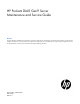
• Four-bay LFF non-hot-plug drive backplane connected to the H240 Host Bus Adapter Item Description 1 Drive power cable 2 Mini-SAS cable Four-bay LFF hot-plug drive cabling • Four-bay LFF drive backplane connected to the system board Item Description 1 Drive power cable 2 Mini-SAS cable Cabling 95
• Four-bay LFF drive backplane connected to a P440 controller in the low-profile expansion slot 1 Item Description 1 Drive power cable 2 Mini-SAS cable • Four-bay LFF drive backplane connected to a H240 adapter in the low-profile expansion slot 1 Item Description 1 Drive power cable 2 Mini-SAS cable FBWC cabling The FBWC solution is a separately purchased option. This server only supports FBWC module installation when an HP Smart Array P-Series controller is installed.
Depending on the controller option installed, the actual storage controller connectors might look different from what is shown in this section.
• FBWC module slot 3 cabling M.
• Slot 2 cable routing (1 port supported when slot 1 is occupied) • Slot 3 cable routing (2 ports supported when slot 1 is unoccupied) Cabling 99
• Slot 3 cable routing (1 port supported when slot 1 is occupied) • Slot 2 cable routing with FlexibleLOM riser (2 ports supported when slot 1 is unoccupied) Cabling 100
• Slot 2 cable routing with FlexibleLOM riser (1 port supported when slot 1 is occupied) HP Smart Storage battery cabling Cabling 101
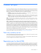
HP Power supply cabling • Item HP 550 W non-hot-plug power supply cabling Description 1 16-pin power supply sideband signal cable 2 24-pin power supply cable • HP 900 W hot-plug power supply cabling Item Description 1 16-pin power supply sideband signal cable 2 24-pin power supply cable 3 Reserved Cabling 102
Optical drive cabling Item Description 1 Optical drive cable 2 Drive power cable Front I/O cabling Item Description 1 Front I/O cable 2 USB 2.
Specifications Environmental specifications Specification Value Temperature range* — Operating 10°C to 35°C (50°F to 95°F) Nonoperating -30°C to 60°C (-22°F to 140°F) Relative humidity (noncondensing) — Operating Minimum to be the higher (more moisture) of -12°C (10.4°F) dew point or 8% relative humidity Maximum to be 24°C (75.2°F) dew point or 90% relative humidity Nonoperating 5% to 95% 38.7°C (101.7°F), maximum wet bulb temperature * All temperature ratings shown are for sea level.
Power supply specifications Depending on the installed options and/or the regional location where the server was purchased, the server is configured with one of the following power supplies: • HP 550 W Power Supply (PN 730941-B21) • HP 800-W/900-W Gold AC Power Input Module (PN 744689-B21). This module is supported when the two-bay HP RPS backplane option (PN 745813-B21) is installed.
Support and other resources Before you contact HP Be sure to have the following information available before you call HP: • Active Health System log (HP ProLiant Gen8 or later products) Download and have available an Active Health System log for 7 days before the failure was detected. For more information, see the HP iLO 4 User Guide or HP Intelligent Provisioning User Guide on the HP website (http://www.hp.com/go/ilo/docs).
providers or service partners) identifies that the repair can be accomplished by the use of a CSR part, HP will ship that part directly to you for replacement. There are two categories of CSR parts: • Mandatory—Parts for which customer self repair is mandatory. If you request HP to replace these parts, you will be charged for the travel and labor costs of this service. • Optional—Parts for which customer self repair is optional. These parts are also designed for customer self repair.
Pour plus d'informations sur le programme CSR de HP, contactez votre Mainteneur Agrée local. Pour plus d'informations sur ce programme en Amérique du Nord, consultez le site Web HP (http://www.hp.com/go/selfrepair). Riparazione da parte del cliente Per abbreviare i tempi di riparazione e garantire una maggiore flessibilità nella sostituzione di parti difettose, i prodotti HP sono realizzati con numerosi componenti che possono essere riparati direttamente dal cliente (CSR, Customer Self Repair).
HINWEIS: Einige Teile sind nicht für Customer Self Repair ausgelegt. Um den Garantieanspruch des Kunden zu erfüllen, muss das Teil von einem HP Servicepartner ersetzt werden. Im illustrierten Teilekatalog sind diese Teile mit „No“ bzw. „Nein“ gekennzeichnet. CSR-Teile werden abhängig von der Verfügbarkeit und vom Lieferziel am folgenden Geschäftstag geliefert. Für bestimmte Standorte ist eine Lieferung am selben Tag oder innerhalb von vier Stunden gegen einen Aufpreis verfügbar.
sustituciones que lleve a cabo el cliente, HP se hará cargo de todos los gastos de envío y devolución de componentes y escogerá la empresa de transporte que se utilice para dicho servicio. Para obtener más información acerca del programa de Reparaciones del propio cliente de HP, póngase en contacto con su proveedor de servicios local. Si está interesado en el programa para Norteamérica, visite la página web de HP siguiente (http://www.hp.com/go/selfrepair).
Opcional – Peças cujo reparo feito pelo cliente é opcional. Essas peças também são projetadas para o reparo feito pelo cliente. No entanto, se desejar que a HP as substitua, pode haver ou não a cobrança de taxa adicional, dependendo do tipo de serviço de garantia destinado ao produto. OBSERVAÇÃO: Algumas peças da HP não são projetadas para o reparo feito pelo cliente. A fim de cumprir a garantia do cliente, a HP exige que um técnico autorizado substitua a peça.
Support and other resources 112
Support and other resources 113
Acronyms and abbreviations ABEND abnormal end AC alternating current AMP Advanced Memory Protection API application program interface ASHRAE American Society of Heating, Refrigerating and Air-Conditioning Engineers CSR Customer Self Repair FBWC flash-backed write cache GPU graphics processing unit HBA host bus adapter HP SIM HP Systems Insight Manager Hz hertz iLO Integrated Lights-Out Acronyms and abbreviations 114
IML Integrated Management Log LFF large form factor NMI nonmaskable interrupt NVRAM nonvolatile memory PCIe Peripheral Component Interconnect Express POST Power-On Self Test PSU power supply unit RBSU ROM-Based Setup Utility RPS redundant power supply SAS serial attached SCSI SATA serial ATA SD Secure Digital SIM Systems Insight Manager SPP HP Service Pack for ProLiant Acronyms and abbreviations 115
TPM Trusted Platform Module UEFI Unified Extensible Firmware Interface UID unit identification USB universal serial bus Acronyms and abbreviations 116
Documentation feedback HP is committed to providing documentation that meets your needs. To help us improve the documentation, send any errors, suggestions, or comments to Documentation Feedback (mailto:docsfeedback@hp.com). Include the document title and part number, version number, or the URL when submitting your feedback.
Index A access panel 34 Active Health System 78 ambient temperature 103 ambient temperature sensor, cabling 102 authorized reseller 105 authorized technician 105 Automatic Server Recovery (ASR) 83 B drive cabling 93 drive carrier 31 drive numbering 91 E electrostatic discharge 23 embedded UEFI diagnostics 80 environmental specifications 103 error messages 76 extending server from rack 27 external USB functionality 82 boot options 79, 80 F C fan blank 44 fan connectors 45, 88 fan location 44 fan modul
HP Insight Diagnostics 81 HP Insight Diagnostics survey functionality 81 HP Insight Online 81 HP Insight Remote Support software 81 HP ProLiant Pre-boot Health Summary 78 HP Smart Storage Battery 37 HP Smart Storage Battery cabling 100 HP SSA (HP Smart Storage Administrator) 82 HP Systems Insight Manager (SIM) 79, 81 HP technical support 6, 105 HP Trusted Platform Module option 75 humidity 103 I illustrated parts catalog 16 iLO account information 84 iLO connector 84 Insight Diagnostics 81 Integrated Light
specifications, mechanical 103 specifications, power supply 104 specifications, server 103 static electricity 23 storage controller 90, 93 symbols on equipment 23 system battery 59 system board components 88 system configuration settings 90 system maintenance switch 90 T technical support 6, 105 temperature requirements 103 TPM connector 88 troubleshooting resources 76 Trusted Platform Module (TPM) 75 U UEFI System Utilities 79 UID button 84 UID LED 84 unit identification (UID) 84 USB connector 84 USB sup