ATTACHMENT F.
••••••••••••••••••••••••••••••••••• CCAASS HHFFSS SSCCAALLEE ••••••••••••••••••••••••••••••••••• USER’S MANUAL
Federal Communications Commission Requirements Warning : Changes or modifications not expressly approved by the party responsible for compliance with the FCC’S rules could void the user's authority to operate the equipment. THIS DEVICE COMPLIES WITH PARTS 15 OF FCC RULES OPERATION IS SUBJECT TO THE FOLLOWING TWO CONDITIONS (1)THIS DEVICE MAY NOT CAUSE HARMFUL INTERFERENCE, AND (2) THIS DEVICE MUST ACCEPT ANY INTERFERENCE RECEIVED, INCLUDING INTERFERENCE THAT MAY CAUSE UNDESIRED OPERATION.
TABLE OF CONTENTS ••••••••••••••••••••••••••••••••••• CHAPTER 1 GENERAL INTRODUCTION •••••••••••••••••••••••••••••••••••••••••• 1 - 1. INTRODUCTION 1 - 2. NAME OF EACH PARTS 1 - 3. SPECIFICATION ••••••••••••••••••••••••••••••••••• CHAPTER 2 PREPARATION FOR OPERATION ••••••••••••••••••••••••••••••••••• 2 - 1. PREPARATION FOR OPERATION ••••••••••••••••••••••••••••••••••• CHAPTER 3 INSTALLATION ••••••••••••••••••••••••••••••••••• 3 - 1.
••••••••••••••••••••••••••••••••••• CHAPTER 1 GENERAL INTRODUCTION ••••••••••••••••••••••••••••••••••• 1 - 1. INTRODUCTION This manual is the specification for the CAS SCALE. Main features are : 1) Four load cell(Full bridge) type. 2) Various capacity. 3) connectable to various indicator.
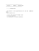
1 - 2. NAME CLASSIFICATION OF EACH MODEL 2HFS33 5HFS44 5HFS45 10HFS44 H-FLOOR SCALE(HFS) 10HFS45 10HFS46 10HFS55 10HFS56 10HFS57 DIMENSION(mm) LOADCELL 914.4x914.4x90(3 x 3 BSA-500L-T x 3 5 ) 1219.2x1219.2x90(4 x 4 x BSA-01-T 3.5 ) 1219.2x1524x90(4 x 5 x 3.5 BSA-01-T ) 1219.2x1219.2x90(4 x 4 x BSA-02-T 3.5 ) 1219.2x1524x90(4 x 5 x 3.5 BSA-02-T ) 1219.2x1828.8x90(4 x 6 x BSA-02-T 3.5 ) 1524x1524x90(5 x 5 x 3.5 BSA-02-T ) 1524x1828.8x90(5 x 6 x 3.5 BSA-02-T ) 1524x2133.6x90(5 x 7 x 3.
* GENERAL SPEC' CLASSIFICATION H-FLOOR SCALE(HFS) MODEL DIMENSION(mm) LOADCELL CAPACITY 1HFS0808 800x800x90 BSA-500L-T 1000 kg 1HFS1010 1000x1000x90 BSA-500L-T 1000 kg 1HFS1012 1000x1200x90 BSA-500L-T 1000 kg 2HFS1212 1200x1200x90 BSA-01-T 2000 kg 2HFS1215 1200x1500x90 BSA-01-T 2000 kg 2HFS1515 1500x1500x90 BSA-01-T 2000 kg 3HFS1212 1200x1200x90 BSA-02-T 3000 kg 3HFS1515 1500x1500x90 BSA-02-T 3000 kg 3HFS1518 1500x1800x90 BSA-02-T 3000 kg 5HFS1515 1500x1500x90 BS
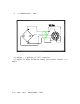
•••••••••••••••••••••••••••••••••••••••••• CHAPTER 2 PREPARING FOR OPERATION •••••••••••••••••••••••••••••••••••••••••• 2 - 1. PREPARING FOR OPERATION 1) Check the power source and match the voltage converting switch to voltage of outlet. 2) Do not put excessive weight on this scale. 3) Keep the scale in dry place. of •••••••••••••••••••••••••••••••••••••••••• CHAPTER 3 INSTALLATION •••••••••••••••••••••••••••••••••••••••••• 3 - 1. COMPOSITION OF HFS A.
which is receiving weight, and •ADJUST FOOT• to support load, and•JUNCTION BOX• sending load cell output to the indicator. B. FUNCTION 1) LOAD CELL Generating electric output proportional to load 2) BODY It's the part to receive the objects which is measured 3) ADJUST FOOT It's the part for supporting load or adjusting level. 4) JUNCTION BOX It calculates each load cell's output and transmits it to the indicator.
4 - 2. SENSITIVITY TEST This is the test for output calibration of load cell. a) weight : a quarter of full capacity. b) Adjust to make deviation among four points within +/-1 digit. 4-3.
a) whiston • • • • bridge EX(+) : Excitation Voltage(+) EX(-) : Excitation voltage(-) SIG(+) : Signal Voltage(+) SIG(-) : Signal Voltage(-) 4- 4.
a) No.1 load cell is connected to V.R.I of box b) the weight deviation among four points should be within +/-1 digit by a quarter of full capacity weight c) When the deviation among four points on the body is over +/-1 digit, adjust variable resister of junction box pertinently (example : If 100kg load is put on the platform, L/C outputs are as follow) L/C : 100.1/ No.2 : 100.2/ No.3 : 99.7 /No.4 : 100.0 Increase No.3 V.R of junction box and decrease No.2 V.