VS2104 8 Channel Wireless NVR with 10.
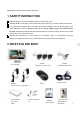
Table of Contents 1. 2. 3. SAFETY INSTRUCTION............................................................................................................................................. 3 WHAT’S IN THE BOX?.............................................................................................................................................. 3 AT A GLANCE....................................................................................................................................................
Please read carefully before using this equipment. 1. SAFETY INSTRUCTION 1 Install the NVR in sufficiently ventilated spaces to prevent plug vents. 2 Install the NVR on a flat wall or other flat surfaces, avoid mounting in a severe vibration environment. 3 Only use the power adapter plug contained in the material supplied since other power adapter plugs could damage the devices. Ensure access to the power adapter plug is not obstructed by furniture or such.
3. AT A GLANCE 3.
Item What it is What it does 1 NVR Screen 10.1” LCD panel 2 Microphone Captures the sound on monitor and transmits the sound from monitor to camera. (Intercom) 3 Power Indicator The indicator LED will turn on when NVR is powered 4 HDD Indicator The indicator LED will turn on when HDD is installed 5 NVR Antenna Transmitting wireless signal with wireless camera. 6 HDMI port Connect the HDMI cable 7 USB port Connect the mouse to control the NVR or connect to USB storage for back up.
3.2 CAMERA 3.2.1 Night Vision Camera Item What it is What it does 1 Microphone Captures the sound on camera side and transmits the sound from camera to monitor. 2 Lens Catches the video in front of the lens and transmits video from camera to Monitor. 3 Indicates the working status of camera.
3.2.2 Floodlight Camera Item What it is What it does 1 Microphone Captures the sound on camera side and transmits the sound from camera to monitor. 2 Lens Catches the video in front of the lens and transmits video from camera to Monitor. 3 Indicates the working status of camera. (Green LED) Working Indicator Flashing rapidly——Ready to pair/ pairing mode Solid green——Paird / working 4 IR LED Infrared LEDs provide viewing in no/low light conditions.
4. SET UP THE HARDWARE 4.1 NVR 1 Place the stand on the back of the NVR on a table or install to other flat surfaces, position the antenna. 2 Connect the mouse to the mouse port on the back of the NVR. 3 Connect an AC adaptor to the power input on the back of the NVR. Connect the other end of the adapter to a standard indoor power outlet. The NVR will power on automatically and start initialize, Please wait until initialization is completed.
Install the Camera(s) 1 Position the camera where you want it, plug it into power, and check video on the NVR. Move the camera if the view is not what you want. 2 Hold the base of the camera stand where you want to mount it and mark the location of the screw holes. 3 Use the included screws and anchors to attach the base to the wall or ceiling. 4 Tug gently on the stand to make sure it is securely in place. 4.
1 Setup New Password The default user name is “admin”. Please enter your new password and confirm the new password. Select Remember Password, the system will remember the password you have set. After confirm the new password, click Next to enter the next step. Note: Password should be 4~10 digits. The password can be letter(s) and/or number(s). Do not use symbols or space in password.
Recording setting type: Continuous, Motion, No Record Left click and drag the table to fill the desired date and time blocks. A. Under Continuous type, the filled blocks are in GREEN. During the filled date and time blocks, NVR will keep recording continuously. B. Under Motion type, the filled blocks are in YELLOW. During the filled date and time blocks, NVR will record once motion is detected. C. Under No Record type, the filled blocks are in blank. D.
After finishing upon setting, then click DONE to complete it and enter to live view screen. 5.2 NVR SCREEN The NVR’s screen has 3 main parts: •Live View area. The main screen area displays live video from the camera(s). • Main menu. Those menus allow you to manage the system. • Icon bars. Most of icons display on the top and bottom of the live view screen. Viewing Modes The Live View area displays live video from the cameras.
Default: 4 CH split screen. NOTE: System is expandable to 8 CH, go to section 7.1 to set 8 CH view. • Single Channel View. Double click the center of the quadrant to enter Single Channel View mode. Under Signal Channel Mode, double left click the screen to exit then back to Quad Mode. • Auto Switch. Move the mouse over the bottom of the display, selected the Auto Switch Icon and click the icon to turn it to blue, NVR will switch each channel automatically in full screen display. 5.2.
Number(camera number) 6 Intercom Click here to activate intercom feature to talk back to the camera. 7 Floodlight Control Click here to turn the camera floodlight on/off manually. 8 Zoom Click the area you would like to zoom. Scroll up the mouse to Zoom in, scroll down to zoom out. 9 Color Adjust Click here to adjust Hue, Brightness, Saturation, Contrast, Sharpness. You can also click the quick setting icon: Default, Bright and Soft.
5.2.3 Main Menu Toolbar Move the mouse cursor to the bottom of the screen, below toolbar will display automatically. Click here: Main menu: click here to enter main menu. Click here to lock the toolbar. When you select the lock, you have to enter your Password and click OK to save the setting. Click this icon again to unlock the toolbar.
7.1 Camera & Display Click 1 , to enter the video managing surface. Cameras Select the camera which you want to set. Modify channel name, enable/disable the audio from camera. 2 Display OSD Alpha: set the brightness of screen background. Click+ to turn dark, click- to turn light. Display resolution: select from 1024*768,1280*1024,1366*768,1440*900,1080p@50Hz, 1080p@60Hz.
1. Click the channel you want to pair the camera to, click Pair. 2. Check the status of camera working indicator: Quick flashing: under pairing mode Slow flashing: unpaired or out of range Solid green: paired Please make sure the camera is powered on, then press and hold the pair button ( on the back of the camera) about 5 seconds until the working indicator light turn off, then wait until the working indicator is flashing quickly, means the camera is ready to pair. 3.
2 Click to add a camera from another 3 cameras. For example, click on the right of CH1, then select CH4. That means, CH4 will transmit the signal through CH1, finally transmit to NVR. Bring both cameras near the NVR to set up the repeater feature. 3 Click Aplply or OK to save the setting, click Refresh to refresh the connecting datas. Click Cancel to return to previous screen. NOTE: You can repeat MAX 2 cameras for a repeater connecting. 4 Delete the repeater camera.
Select the Channel you want to set. Copy To Select here copy the same setting to all channels. Select the type of recording you’d like to activate Recording setting type: Continuous, Motion, No Record Left click and drag the table to fill the desired date and time blocks. E. Under Continuous type, the filled blocks are in GREEN. During the filled date and time blocks, NVR will keep recording continuously. F. Under Motion type, the filled blocks are in YELLOW.
Select channel from 1-8, you can select the channel you would like to review. You can also select several channels a time and filter the video out. When filtering the video, system loads up to 4 channels at a time. 3 Select Continuous, filter the videos under continuous recording mode. 4 Select Motion, filter the videos under motion recording mode. 5 Click Search to load the recorded file, among the file list, select the file you’d like to play, click File Playback to play it.
7.4 Light Setting Light setting (only available when the monitor connects to VC2000L floodlight camera) Click , to enter light settings section. Select the Channel you want to set. Duration: click here to set how long the light should be switched on after the movement has been triggered. You can turn off the light or set it to 1/3/10 min. Dimmer: Adjust the brightness of the LED lamp Timer: Slect Dusk to Dawn, the light will be turned on dusk and turn off dawn automatically everyday.
7.5 Motion & Alarm Click , to enter the video detection setting. Select the channel you want to set. Set the sensitivity of the VMD sensor: Highest-High-Medium-Low-Lowest Highest: motions are more easily detected. Lowest: motions are least easily detected. PIR enable: default value is selected. NOTE: Motions except human actions, such as shades of trees etc also will be detected then alarm, select PIR enable will decrease those alarm.
After set up the mask area, click the “Return” to save and exit. Audio Alert: select here, audio alert will be heard from NVR once motion is detected. Push notification: select here, you will receive a push notification from your smart phone once motion is detected. 7.6 Hard Drive , to enter HARD DRIVE setting surface. Click HDD SETUP: This surface will show the space of HDD (total space/used space/free space). Select overwrite, system will overwrite files when HDD is full.
If above 1, 6 and 11 channel still not working, you may have to try one by one to find the most appropriate channel. 7.8 Advanced Click 1 , to enter advanced setting surface. Maintenance. Auto Reboot: Determine how often an auto reboot will occur. Schedule: Schedule the reboot frequency. Next Reboot: Shows the date and time of the next reboot. Reboot: Manually reboot the NVR. Shut Down: Click to turn off the NVR operation system.
Connect the NVR to your router using an Ethernet cable so that it has an Internet connection. 8.2 APP Remote 8.2.1 Add camera 1 Touch the App icon “WNVR Pro” to launch the app. 2 Add the Devise UID of your NVR to App. Go to NVR Main Menu-SYSTEM-Info to find the UID of NVR. There are 2 ways to add the UID. ADD, tap here to input UID manually. SCAN, tap to scan the QR code showing inside the NVR or on the back of the NVR label. (Recommended) 3 Below surface displays after adding the UID.
Device name: change the device name to what you want. User name: default user name: admin, the user name is the same as the NVR Password: input the password (the password should be exactly the same as what you have set on NNR). Channel number: select the channel number, this means the total channel which the App will display. If your only have 4 cameras, you can choose 4 channel display. If you add more cameras to the system, you can choose 8-CH.
QUAD VIEW→SINGLE VIEW b) Settings Tap to enter this surface. Tap Setting, to turn on/ff the 2G/3G/4G network remind, to view the mobile data traffic statistics or empty data, to select preview mode. Tap Screenshot/Recording to enter the file list, you can tap to view/play back the video or delete the file. Tap Help to review the preview of your device and review troubleshoot section. Version: Display the current App version.
8. SPECIFICATIONS Monitor LCD Screen Video Audio Record Hard Disk Wireless parameter External interface Screen size 10.1” Resolution 1024(H)×600(V) Video input 4x1296p. System expandable to 8 x 1296p. Video format H.265 Audio output Built-in speaker Audio format G7.11A Two way audio Yes Recording resolution 720p/960p/1296p Recording mode Continuous recording, motion recording Type 1 SATA port,2.5 inch HDD Wireless transmission 300Mbps Transmission standard 2.4GHz IEEE 802.
Wireless Camera Resolution 300W 2304*1296 Sensor 1/2.7" CMOS sensor Minimum illumination 0.02Lux @(F1.8,AGC ON) , 0 Lux with IR Lens Viewing Angle (horizontal) Viewing Angle (Diagonal ) Camera Day & night switching mode LED Lighting LED Luminance VMD detection Night fill light mode & distance Video compression standard Compression Video compression bit rate standard Stream parameters Function,Performance External interface Others 2.8mm(night vision camera) 3.
9. TROUBLE SHOOTING If… Try… Ref. Section… Forget Password Go to NVR to reset the password 5.2.2 Log In & Forget the NVR password. Forget the password to Password access the App. Can’t Connect to the App Make sure NVR is connected to your / local router by Ethernet cable. Make sure video display normally on the NVR. Can’t Recording Make sure the HDD is well inserted. Enter MAIN MENU-HARD DRIVE 7.
10. FCC REGULATIONS Part 15 Compliance Statement This device complies with Part 15 of the FCC Rules. Operation is subjected to the following two conditions: (1) this device may not cause harmful interference, and (2) this device must accept any interference received, including interference that may cause undesired operation. Privacy of communication may not be ensured when using this device.