
User's Manual

CONFIGURATION
The Configuration web page contains information and configurable parameters pertaining to the
operation of the product. The first line of information on the Configuration screen is a repeat of the
Device Type from the Status web page. The following are the parameters and their descriptions.
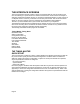
Timing Mode: choose whether this module will be a timing master or a timing slave. If the
operator is changing this mode, change only this parameter, save the changes and reboot. Upon
reboot different set of web based interface pages will present themselves and offer the operator
different manageable as well as configurable features.
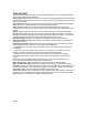
Sync Input: choose the type of synchronization that this access point module will utilize. If “Sync
to Received Signal” is chosen, then it is assumed that:
this access point module it connected to a Cluster Management Module and will be
receiving a sync pulse via GPS
this access point module is connected to another access point module that is generating its
own sync pulse.
If “Generate Sync Signal” is chosen then it is assumed that:
this access point module is a stand-alone module with no other access point modules
within a 5 mile radius.
this access point module is generating the sync pulse for a cluster of access point modules
and there are no other access point modules within a 5 mile radius.
Link Negotiation Speeds: choose the type of link speed desired for the Ethernet connection.
The default for this parameter is for all the choices to be checked.
RF Frequency Carrier: choose the frequency that the module will transmit on. The default from
the factory is to have this parameter set to none.
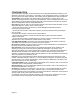
Downlink Data: choose the percentage of the aggregate throughput that is needed for the
downlink (i.e going from the access point module to the subscriber). For example, if the
aggregate throughput on the access point module is 6 Mbits, then configuring this parameter for
75% will allocate 4.5 Mbits for the downlink and 1.5 Mbits for the uplink. If the access point
module is in a cluster with other modules then this parameter on all units must be set exactly the
same. The default for this parameter is 75%.
LAN 1 IP: enter in the IP address that will be associated with the Ethernet connection on this
module. The default address is 169.254.1.1. If the IP address is forgotten, the operator will need
physical access to the module and will need to create a Cyclone “default plug”. See steps at the
end of this section for use of a default plug.
LAN1 Subnet Mask: enter in an appropriate subnet mask for the module to “talk” on the network.
The default value for this parameter is 255.255.255.0
Default Gateway: enter in the appropriate gateway for the module to “talk” on the network. The
default for this parameter is 169.254.1.1.
Private IP: the default for this parameter is 192.168.101.1. It is recommended that the operator
not change this parameter. A flat, class C subnet is used to communicate with each of the
subscriber modules that have registered. The access point utilizes a combination of the private IP
and the logical unit ID (LUID) of the subscriber module.
For example, if there are two subscriber modules (LUID 2 and LUID 3) registered to an access
point module, then the access point uses the following to communicate to each:
Page 10