
User's Manual

4
3.2 COLLOCATION OF 5.8 GHZ OFDM WITH STANDARD 5.7 GHZ CANOPY FSK
When locating Cyclone OFDM (5.8 GHz) APs near 5.7 GHz standard Canopy FSK APs (especially on the
same tower, but also in the same geographical area), the following practices should be followed to avoid
interference between the two systems:
Plan spacing between OFDM and FSK channels to provide 25 MHz center spacing, which gives a
10 MHz guard band between the 10 MHz OFDM channel and the 20 MHz FSK channel.
Coordinate Downlink Data %, Range, and Control Slot settings using both the OFDM and the
FSK frame calculators. The following paragraphs give more details on these recommended
practices.
3.3 CHANNEL SPACING
Center spacing of 25 MHz between collocated FSK and OFDM APs provides a 10 MHz guard band
between the 20 MHz and 10 MHz channels, which has proven useful and needed in field testing.
Alternatively, in cases where channel planning is severely restricted and the 10 MHz guard band (25 MHz
spacing) is not possible, using vertical separation of 5 feet or more between the OFDM and FSK APs may
allow collocation with no guard band (15 MHz spacing) in some deployments.
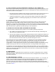
3.4 FRAME CALCULATIONS AND CONFIGURATION SETTINGS
Interference between collocated Canopy systems can be avoided by following two practices:
1. Use a CMM. This synchronizes frame start, so that all collocated APs begin transmitting at the
same time each 2.5 millisecond frame.
2. Use the frame calculators in each module, OFDM and FSK (the frame calculators are different, as
frame details are different) to select Downlink Data %, Range, and Control Slots for each system
that produce “Rec SEQ Start” values that are within 300 bit times. This ensures that all collocated
APs end transmission each frame before any collocated AP begins to receive.
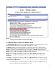
When collocating only Canopy OFDM APs together, or collocating only Canopy hardware scheduled
FSK APs together, the simple practice of setting the Downlink Data %, Range, and Control Slots the
same on all APs ensures they won’t interfere with each other. (These parameters are set on the
“Configuration => Radio” page of the AP.) However, due to the different “physical” layer between Canopy
OFDM and Canopy FSK, this doesn’t necessarily work when co-locating OFDM and FSK together.
You will need to use frame calculators on both the OFDM and FSK modules, as they are different frame
calculators. For the same Downlink Data %, Range, and Control Slots, the frame calculators give different
results. Use of the frame calculators is similar to the previous use when co-locating software-scheduled
and hardware-scheduled APs.
4 CONFIGURING
Most PMP 430 Series configuration items are identical or very similar to configuration items in standard
FSK Canopy modules. This section discusses those that are new or changed and also remarks on some
that remain unchanged.
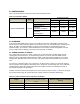
4.1 LINK OPERATION – 1X/2X/3X
Cyclone 5700-360.OFDM Series products offer three levels or speeds of operation – 1X, 2X, and 3X. 3X
supports a typical maximum aggregate (sum of up and down) throughput of up to 21 Mbps. If received
power is less due to distance between the AP/BHM and the SM/BHS or due to obstructions, or
interference affects the RF environment, the Canopy system will automatically and dynamically adjust
links to the best operation level. Distance, rates and other information associated with the operation levels
are shown in Table 1.