
Installation Guide

Key Hole Slot
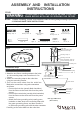
ASSEMBLY AND INSTALLATION
INSTRUCTIONS
NOTES 1 Before installing consult local electrical codes for wiring and grounding requirements:. , .
2. READ AND SAVE THESE INSTRUCTIONS
Outlet Box
House Grounding Wire
Wire Connector (E)
Fixture Mounting Screw D()
Ceiling Pan
Socket
Coupling
Tube I()
Glass Shade
Metal Pad J( )
Nipple H()
Hex Nut K()
Cover G()
Finial F()
Mounting Strap A()
Green Grounding Screw C()
Mounting Screw B()
Nipple H()
Tube W Threaded Pipe I/()
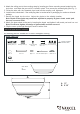
Hardware Package (included):
Mounting Screw B()
Green Grounding
Screw (C)
Wire Connector (E)
Mounting Strap A()
Fixture
Mounting Screw D()
Metal Pad J( )
Hex Nut K()
Cover G()
Finial F()
171106
WARNING:
TO AVOID RISK OF ELECTRICAL SHOCK BE SURE TO SHUT OFF,
POWER BEFORE INSTALLING OR SERVICING THIS FIXTURE.
Turn off the power at fuse or circuit box
Type A Max 60 W.
or ST Vintage Bulb
()not included
Threaded Pipe
on the mounting strap and screw them in 2 to,
3 turns.
2 Attach the mounting strap to the outlet box.
using two mounting screws.
3 Pull out the source wires from the outlet box..
Make wire connections using wire connectors
---Connect the hot wire (usually black insulation)
from the fixture to the black wire from the power
source.
---Connect the neutral wire (usually white insulation)
from the fixture to the white wire from the power
source.
---Attach the fixture grounding wire (usually green
insulation or bare wire) to the mounting strap with
the green grounding screw, and then connect it
to the house grounding wire with the .wire connector
Carefully put the wires back into the outlet box.
(Not included)
Bulb Type A Max.60 W
Installation Steps
1. Attach the two fixture mounting screws to the holes
Screw
as follows:
Fig.1.
C0149