
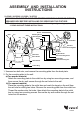
Installation Guide

100525
ASSEMBLY AND INSTALLATION
INSTRUCTIONS
WARNING: BE SURE TO SHUT OFF POWER AT THE MAIN FUSE OR CIRCUIT
BREAKER BOX BEFORE INSTALLING OR SERVICING THIS FIXTURE.
NOTE: 1. Before installing, consult local electrical codes for wiring and grounding requirements.
2.
READ AND SAVE THESE INSTRUCTIONS
.
VL55402 / VL55502 / VL55602 / VL55702
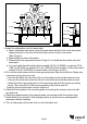
V-B1
V-B3
V-C
V-C
V-E
Glass Shade
Glass Holder
Mounting Plate
Dry Wall Screw
Set Hole
House Grounding Wire
Wire Nut
Outlet Box
Green Grounding Screw
Fixture Wire
Fixture Grounding wire
Screw
Mounting Screw
Anchor
Back Plate
Bolt Nut
Socket Ring
Figure 1
1. Unscrew two bolt nuts, and remove the mounting plate from the back plate.
2. Fix the mounting plate to the wall.
a) For wooden material:
Attach the mounting plate to the outlet box by using two mounting screws, and
then secure the dry wall screws through the set holes to the wall.
b) For cement material:
Place the mounting plate to the outlet box and mark the target on the wall from
the set hole for drilling two holes. Remove the mounting plate from the outlet box.
Thread the anchors into the holes, then attach the mounting plate to the outlet
box by using two mounting screws. Secure the dry wall screws through the set
holes into the anchors.
Page 1
Bulb Type A Max.100W
(not included)