
Installation Guide

Synchronous control:
If multiple sensor control units are used within a single series, you can swipe your hand (or any object) under the
detection zone of any of the sensor units, and all light fixtures will be controlled synchronously.
1. The combined wattage of multiple light fixtures per run should not exceed the power rating of the driver (maximum 36W).
2. A minimum distance of 3˝ between light fixtures should be allowed for linking cord. Install each light fixture by following steps
9-12 of the instructions. Once installed, attach linking cords between each light fixture. (See Fig. 9)
3. If the linking cord sags: Peel away the waxed paper on the cable clip and stick to the bottom of the under cabinet. Fasten the
12" linking cord with the cable clip. (See Fig. 9)
Page 3 / 4
150414
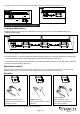
Linking multiple fixtures:
Multiple light fixtures can be linked up to a single driver by using a mini connector or by using additional linking cords.
A. Using 12˝ linking cord:
Fig.9.
Outlet
36W Driver (A)
Fig.7.
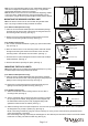
Turn on the power at the main fuse or circuit breaker box.
12" Linking Cord (B)
Metal Disk (D)
Fig.8.
Cable Clip
14. Plug the connector into the sensor and plug the driver into a 120V AC 60HZ outlet. (See Fig. 8)
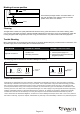
Operation
Wave hand under sensor once to
turn light on and off.
TURNING LIGHTS ON, OFF.
ACTIVATING SAFE EXIT.
Wave hand under sensor twice,
Light will flash, then gradually
dim-to-off in 1 minute.
DIMMING LIGHTS
Hold hand under sensor to adjust
brightness.
1x
2x
Note: Detection zone is within 4 inch distance from the sensor.