
Owner manual


IOM-31-N
05-14
MODEL 31-N
Pressure Reducing Service Regulator
SECTION I
II. INSTALLATION
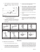
1. An inlet block valve should always be installed.
An outlet block valve is recommended.
2. If service application is continuous such that
shut down is not readily accomplished, it is
rec om mend ed that an outlet block valve and a
manual bypass valve be installed.
3. Pipe unions are recommended to be installed to
allow removal from piping. Trim can be changed
without removal from pipeline.
4. An outlet pressure gauge should be located
ap prox i mate ly 10 pipe diameters downstream,
and within sight.
5. All installations should include a downstream
re lief device if the inlet pressure could exceed the
pressure rating of any downstream equipment.
A downstream safety relief valve or a rupture
disc is absolutely required if the inlet P
1
pres sure exceeds 100 psig (6.9 Barg) under
any normal or upset conditions.
SECTION II
I. DESCRIPTION AND SCOPE
The Model 31-N is a pressure reducing service regulator used to control downstream (outlet or P
2
) pressure to levels
between 2" – 16 “WC (50–400 mm H
2
O). Sizes are 1/2" 3/4”, 1", 1-1/2" and 2" (DN15, 20, 25, 40 and 50).
The unit is designed for gaseous service only.
Refer to Technical Bulletin 31-N-TB for sizing, application and selection recommendations.
INSTALLATION, OPERATION & MAINTENANCE MANUAL (IOM)
WARNING
1. Model 31-N does not include an internal relief mech a nism. Overpressure protection requires use of a downstream
safety relief valve or rupture disc.
2. User to determine acceptance of non-relieving design by federal, state, and/or local codes.
3. IF GAS IS DETECTED BY SMELL, CONTACT YOUR GAS COMPANY IMMEDIATELY.
4.
User to comply with instructions, operating re quire ments and maintenance requirements located herein the “IOM-31-N”.
WARNING
The maximum outlet pressure listed on the name plate is
the “upper operative limit” for the sensing di a phragm.
Higher pressures could damage the internals. (Field hy-
dro stat ic or pneumatic pressure tests fre quent ly destroy
diaphragms. DO NOT HY DRO STAT IC OR PNEUMATIC
PRESSURE TEST THRU AN IN STALLED UNIT EX POS ING
THE OUTLET POR TION OF THE REGULATOR TO PRES-
SURES GREATER THAN 50 PSIG (3.45 BARG) FAIL URE
TO HEED MAY RESULT IN CAT A STROPH IC FAIL URE WITH
FLYING PARTS AND POSSIBILITY OF PER SON AL INJURY!
ISO LATE FROM TEST.)
CAUTION
Installation of adequate overpressure pro tec tion is recom-
mended to pro tect the reg u la tor from overpressure and
all down stream equip ment from damage in the event of
regulator failure.
CAUTION
For welded installations, all internal trim parts, seals and
diaphragm(s) must be removed from reg u la tor body prior to
welding into pipeline. The heat of fusion welding will dam-
age non-metallic parts if not re moved. NOTE: This does
not apply to units equipped with extended pipe nip ples.