
Owner manual


IOM-31-N
3
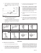
3. Model 31-N includes a linkage lever in its mech a-
nism. The linkage lever allows the regulator to
operate fl ow-to-open (FTO) and provides plug
travel multiplication thru the lever length ratio.
5. Aspiration (jet) effect is developed by properly
locating the “windows” of the loading ring. When
properly po si tioned, a high velocity path is in tro -
duced. This causes a corresponding decrease in
static pressure to be de vel oped at a location that
allows this decreased pressure to register into the
lower case and beneath the diaphragm. The net
result is to pull the diaphragm down and open the
valve port, providing higher unit capacity.
6. A complete diaphragm failure will cause the reg u -
la tor to fail open.
SECTION IV
IV. STARTUP
1. Assure that the proper range spring is indicated
to be within the regulator by inspection of the
unit’s name plate. Apply setpoint pressures that
are only within the stated range.
2. When stating direction of rotation of the ad just ment
screw, the view is with respect to looking down
towards the closing cap or its normal lo ca tion.
3. Start with the block valves closed. A bypass
valve may be used to maintain outlet pressure
in the down stream system without changing the
fol low ing steps.
4. Remove closing cap on top of spring chamber.
Relax the range spring by turning the adjustment
screw CCW a minimum of three (3) full rev o lu tions.
This reduces the outlet (downstream) pres sure
setpoint.
5.
Crack open the outlet (downstream) block valve.
6. Slowly open the inlet (upstream) block valve ob-
serv ing the outlet (downstream) pressure gauge.
Partially close off the bypass valve, if open. De-
ter mine if the regulator is fl owing. If not, slowly
rotate the regulator adjustment screw CW until
fl ow begins.
7. Continue to slowly open the inlet (upstream) block
valve until fully open.
8. Continue to slowly open the outlet (downstream)
block valve, especially when the downstream pip-
ing system isn’t pressurized. If the outlet (down-
stream) pres sure exceeds the desired pressure,
close the inlet (up stream) block valve fi rst, then
the outlet (downstream) block valve, and go to
Step 4, then return to Step 6.
9. When fl ow is established steady enough that the
outlet (downstream) block valve is fully open, begin
to slowly close the bypass valve if installed.
10. Develop system fl ow to a level near its expected
normal rate, and reset the regulator setpoint per
Section VII.
11. Reduce system fl ow to a minimum level and ob-
serve setpoint. Outlet pressure may rise from the
set point of Step 10. The maximum rise in outlet
pressure on decreasing fl ow should not exceed the
stated upper limit of the range spring by greater than
10%; i.e. 5.5–8.0 “WC (140–200 mmH
2
O) range
spring, at low fl ow the outlet pressure should not
exceed 8.8 “WC (224 mmH
2
O). If it does, consult
factory.
SECTION V
V. SHUTDOWN
1. On systems with a bypass valve, and where sys-
tem pressure is to be maintained as the reg u la tor
is shut down, slowly open the bypass valve while
closing the inlet (up stream) block valve. Fully
close the inlet (up stream) block valve. (When on
bypass, the system pres sure must be con stant ly
observed and manually reg u lat ed.) Close the outlet
(downstream) block valve.
2. If the regulator and system are to both be shut-
down, slowly close the inlet (upstream) block
valve. Close the outlet (downstream) valve only
if regulator removal is required.
WARNING
Do not walk away and leave a bypassed reg u la tor
un at tend ed.