
User guide


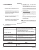

Outlet
@ P2
Port “B”
IAS @
60-100
psig
MODEL
764P
Port “A”
EXH
REV
SIG
“Output”
LOAD
P/P
Blowdown - Drain
Blowdown - Drain
(Shaded portion for steam/condensate systems)
PC
PI
PCV
Bypass
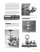
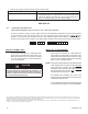
II. INSTALLATION
1. A block valve of the globe/needle type should be
installed at the location of the pressure tapping.
Ball, butterfl y or gate valves are not rec om-
mend ed.
2. Recommended sensing tap pipe size is 1/2"
(DN15).
3. Location of pressure sensing tap should be in a
zone not subject to fl ow disturbances. Rec om-
mend a min i mum of 10 pipe diameters upstream
and 10 pipe diameters down stream from any
elbow, tee, valve, etc. that disturbs fl ow.
4. A pressure gauge is recommended at the location
of each tapping. Differential pressure designs
may in cor po rate a differential pressure gauge.
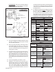
5. A pigtail siphon is required for hot condensing
fl uids, such as steam, to assure a liquid trap at
the controller. The siphon should be installed as
near to the pressure connection(s) on the control-
ler’s diaphragm hous ing as practical.
Figure 1: Recommended Piping Schematic for Pres sure
Reducing Control Valve with Positioner
I. DESCRIPTION AND SCOPE
The Model 764P is a pressure controller used for sensing static pressure, and outputting a pneumatic signal pro por -
tion al to the deviation from the setpoint.
The Model 764PD is a differential pressure controller used for sensing two static pressures (“HIGH” and “LOW”),
and outputting a pneumatic signal proportional to the deviation from the setpoint.
With proper materials selection, the units are suitable for gaseous, liquid or steam service. Refer to Tech ni cal Bulletin
764P-TB for design con di tions and selection rec om men da tions.
Use of oxygen gas as the IAS for a 764P or 764PD is outside the scope of this IOM, and is considered “special
construction”.
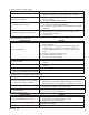
Abbreviations Utilized:
CCW – Counter Clockwise P1 – Inlet Pressure P/P – Pneu mat ic-to-Pneu mat ic
CW – Clockwise P2 – Outlet Pressure REV – Rev o lu tion or Re verse
DIR – Direct PB – Proportional Band SIG – Sig nal
EXH – Exhaust PC – Pressure Controller SRV – Safe ty Relief Valve
IAS – Instrument Air Supply PCV – Pres sure Control Valve TR – Con den sate Trap
PI – Pres sure Indicator V – Vent
SECTION I
MODEL 764P & 764PD
PNEUMATIC PRESSURE CONTROLLERS
INSTALLATION, OPERATION & MAINTENANCE MANUAL (IOM)
IOM-764P / PD
12-13
TR
Supply
Supply @
P1
DIR
TR
Supply
Airset
SRV
PROCESS
Pigtail
Siphon
V
SECTION II