
User guide


IOM-764P / PD
2
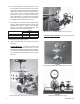
Figure 3
With Option -23; Field Bracket Mounting to Structure
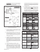
Field Pipe Nipple Mounted. Recommend pipe tap
on top or side of pipe.
Figure 4
Output Pipe Nipple Mounted to Model 2266 Control Valve
Figure 5
Field Pipe Nipple Mounted to Piping
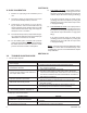
6. It is recommended as a good practice to locate
the controller as close as practical to the pressure
tapping and at a similar elevation. For installations
where the controller was factory mounted on a
control valve unit, the pressure tapping should
be within 6 - 10 feet (2 - 3 meters) of the control
valve. (Remember to compensate for tappings
located above the elevation of the controller for
any liquid pressure head that may occur.)
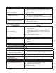
7. The controller’s pneumatic output signal (SIG)
piping or tubing should be limited in length, and
con sid er ation must be given for the ultimate
pur pose of the SIG at its fi nal destination. The
fol low ing are recommended practices:
8. 764P controllers may be mounted by various
meth ods:
Bracket Mounted. Includes a bracket with
ma chine screws to allow attachment to a fi xed
struc tur al ap pend age; requires specifying Option
-23. (This is the method utilized when the 764P/
PD is spec i fi ed to be mounted to a control valve
ac tu a tor.)
Figure 2
Factory Bracket Mounted to Ranger QCT Control Valve
Purpose
Tubing
Size Max Length*
SIG to Positioner
1/4" O.D.
100 ft.
SIG to Supply Booster
1/4" O.D.
100ft.
LOAD to Actuator
1/4" O.D.
10 - 12 ft.
* Contact factory for longer lengths.