
User guide


IOM-764P / PD
3
much oil and water as possible, as well as particles
over 20 microns. Desiccant dried air is absolutely
required for outdoor installations ex posed to freez-
ing temperatures.
14. For 764PD the system must be designed such that
the “HIGH” pressure is always at a higher value
than the “LOW” pressure is at the same time. If
the expected HIGH and LOW pressures reverse
with respect to each other, the unit will become
inoperative, and the output will increase towards full
IAS pressure of 18–20 psig (1.24–1.38 Barg).
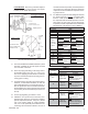
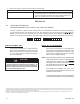
Countersink hole
for #10-32 fl at heat
machine screw.
Figure 6
Panel Mounted Assembly View
INSTALLED ASSEMBLY
(Bottom View)
PANEL CUTOUT
(Front View)
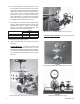
9. It is recommended that a 764PD be bracket or panel
mounted. A 764PD can be pipe nipple mounted
from 1/4" NPT connection.
10. Clean the piping and tubing of all foreign materi-
als including chips, burrs, dirt, etc., prior to use.
Use care in applying thread sealant or TFE tape
to prevent excess material from entering the con-
nect ing pipe or tubing.
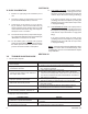
11. Controllers may be oriented in any position in doors.
Outdoors, recommended locations are with the
main lon gi tu di nal axis in a horizontal position, or
with the pneumatic sensor head directed down-
wards. Exhibit care to assure rainwater is pre vent ed
from entering the unused exhaust port (Port A or
Port B).
12. Connect piping/tubing per Tables 1 and 2.
13. 764P/PD’s can operate with a lubricated, non-
dried air supply. However, good practice and other
system com po nents (airsets, , relays, etc.) dictate
use of the highest quality air supply avail able.
If air can not be practically dried and bears oil,
coalescing fi lters should be utilized to remove as
Panel Mounted. Not factory provided. Requires
fi eld provision of a panel opening and support
bracket per the below dimensions:
* Common applications
Uncommon applications
Adjusting Screw
Panel
#10-32 fl at head
machine screw and nut
#10-32 machine
screws
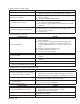
TABLE 1
Controller
764P
Action
IAS to Port
Direct
Reverse
A
Supply
Exhaust
B
Exhaust
Supply
Process
Pressures
Above Atm.
Pressure
Increase in
pressure Increases
output signal
Increase in
pressure Decreases
output signal
764PD
Increase in
differential pressure
Increases output
signal
Increase in
differential pressure
Decreases output
signal
Controller
764P
Action
IAS to Port
Direct
Reverse
B
Supply
Exhaust
A
Exhaust
Supply
Vacuum
Process
Below Atm.
Pressure
Increase in
vacuum
Increases output
signal
Increase in
vacuum
Decreases output
signal
NOTE: 764PD cannot be utilized in vacuum service.
TABLE 2
Controller
Pressure Reducing Applications
Actions
IAS to Port
Control Valve Controller
B *
ATO-FC
(REVERSE)
Reverse-
Increase in pressure
decreases output signal.
Valve "fails closed".
A
ATC-FO
(DIRECT)
Direct-
Increase in pressure
increases output signal.
Valve "fails open".
Back Pressure/Relief Applications
Actions
B *
ATC-FO
(DIRECT)
Reverse-
Increase in pressure
decreases output signal.
Valve "fails open".
A
ATO-FC
(REVERSE)
Direct-
Increase in pressure
increases output signal.
Valve "fails closed".