
User guide


IOM-764P / PD
4
SECTION III
III. PRINCIPLE OF OPERATION
1. The 764 controllers employ laminar fl ow to
pro duce the 3-15 psig (nominal 0.2–1.0 Barg)
output signal. Lam i nar flow eliminates the
need for range springs, levers, pivots and
other parts that pro duce friction and lost motion.
2. The sensing diaphragm in the 764P and 764PD
has a high spring rate and any change in the
sensed pressure produces a minute diaphragm
movement which strokes the sensor plate.
The sensor plate, in turn, throttles the fl ow
of in stru ment air through the sensor to de-
velop the 3-15 psig (0.2-1.0 Barg) output signal.
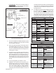
3. On direct acting 764P controllers (see Figure 7) the
supply air enters PORT A and passes through the
pro por tion al band restriction. With an increase in
the con trolled pres sure the fl ow through the sen-
sor is reduced which in creas es the output signal.
The proportional band restriction regulates the
fl ow rate of supply air into PORT A. PORT B is
the ex haust port. A 764PD op er ates the same.
4. On reverse acting 764P controllers (see Figure
8) the supply enters PORT B (not PORT A). With
an increase in the controlled pressure, the supply
air fl ow ing through the sensor decreases, which
re duc es the output signal. The proportional band
restriction regulates the fl ow of exhaust through
PORT A. A 764PD operates in a similar manner.
5. Closing (CW rotation) the proportional band ad just-
ing screw re duc es the proportional band. Open-
ing the screw in creas es the pro por tion al band.
6. The setpoint adjustment positions the sensor so
the diaphragm must defl ect its maximum for its
highest con trolled pres sure setting and hardly
de fl ects for the lowest con trolled pressure setting.
SUPPLY AIR
OUTPUT SIGNAL
EXHAUST (VENT)
LOWER SENSED PRESSURE
HIGHER SENSED PRESSURE
4
4
4
4
4
4
4
4