
User guide


IOM-764P / PD
6
7. Remove the three sensor O-rings (5) from the
sensor (2.1).
NOTE: Typically, additional dis-assembly of
the sensor sub-assembly (2) is not required.
If it is necessary to replace any of the sensor
sub-assembly parts (2.1, 2.2, 2.3, 2.4, 2.5) a
complete new sensor sub-assembly must be
installed. Contact the factory for assistance.
8. Take all the metal parts except the gauge (11)
and nameplate (10) and clean in suitable solvent.
Clean and air blow all drilled air passages.
9. Install pressure gauge (11) into the pneumatic
hous ing (1) using suitable thread sealant.
10. Install new O-rings (5) on sensor sub-assembly
(2). Check the two dimensions given in Figure 10
of the sensor sub-assembly as “fi nal set tings”.
2. Remove cap screws (19) and nuts (18). Re move
diaphragm upper case (13) and upper diaphragm
O-ring (16). Remove diaphragm (12), and SST
diaphragm cover (17) if sup plied. Remove lower
case diaphragm O-ring (16) and pusher post O-ring
(23) for 764PD. In spect for any corrosion damage
and/or per ma nent deformation of the diaphragm
(12) and diaphragm cover (17); if bent, replace.
3. For 764PD, separate at the screwed joint between
the diaphragm lower case (14) and the adapter (21)
turning the diaphragm case (14) CCW (viewed from
di a phragm case end). When separated, remove
the adapter O-ring (22) and replace. Reinstall the
adapter (21) and diaphragm lower case (14).
4. For the 764PD, replace diaphragm O-ring (16) for
the lower case (14) and the pusher post O-ring
(23).
5. Replace diaphragm (12) and diaphragm cover(s)
(17), if supplied. Assure that the di a phragm cover
(thin SST material) (17) is placed on side(s) ex-
posed to the process fl uid(s). (764PD requires both
sides to be cov ered, if supplied with diaphragm
covers (17).
6. Replace with new upper case diaphragm O-ring
(16), upper case (13), and cap screws with nuts
(19 and 18).
7. Recalibrate per Section VI.
C. Pneumatic Circuit Overhaul:
1. Remove output pressure gauge (11) and test
cal i bra tion. If gauge is off ± 2 psi (±0.14 Bar)
recommend replacement.
2. Remove lower diaphragm case (14) from the
pneu mat ic housing (1) at the point where screwed
to geth er. Rotate the diaphragm case (14) CCW
(viewed from di a phragm case end) to loosen. For
764PD: Remove adapter (21) together with lower
diaphragm casing (14) at the screwed joint be-
tween the pneumatic hous ing (1) and the adapter
(21). Rotate the adapt er (21) CCW (viewed from
diaphragm case end) to loosen. Once loos ened,
ori ent the unit along a hor i zon tal axis to pre vent
internal parts from fall ing from within when sepa-
rated. DO NOT RE MOVE PUSHER-POST (24)
FROM 764PD.
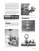
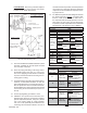
3. Remove sensor plate (15.1) (15).
4. Remove nameplate screw (9), nameplate (10),
and four housing screws (8). Grasp the sensor
sub-assembly (2) end plate (2.2), and pull it
outwards from the housing (1). Watch for the
sensor pin (2.4) as the sensor sub-assembly
(2) is withdrawn, as pin (2.4) easily falls out and
could be lost.
Figure 9: Sensor Sub-Assembly (2)
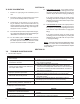
5. Remove sensor plate O-ring (6).
6. Take note of the position of the PB needle
valve (3) by rotating it CW until it seats: count
the exact amount of rotation in 1/8 rev. in cre-
ments; record the count in Table 3. Re move
the PB needle valve (3) with O-ring (7) by
rotating CCW. Remove O-ring (7).
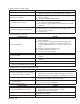
TABLE 3
Part
DESCRIPTION
OF ROTATION
NO. OF
REVOLUTIONS
PB Needle
Valve (3)
No. of Revolutions rotated CW to
fully seat