
User guide


IOM-764P / PD
7
X
5/16”
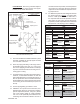
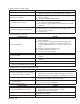
X = 1-27/32" (46.8mm) all ranges
except 50–150 psig = 1-25/32" (45.2mm)
Figure 10
Sensor Sub-Assembly
Assemble per these Dimensions
Figure 11
12. Install the nameplate (10) and nameplate
screw (9).
13. Install the PB needle valve (3) with a new
O-ring (7). Screw the needle valve (3) CW
until seated, then back out to same position
re cord ed in Table 3 prior to dis as sem bly.
14. Place a new sensor plate O-ring (6) down into
the housing (1) cavity next to the end of the
sensor (2.1). Slide the sensor plate (15) into
the housing (1); the fl at portion of the sensor
plate (15) should seat against the O-ring (6).
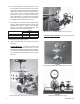
11. Slide the sensor sub-assembly (2) back into
the hous ing (1) so as not to damage the sensor
O-rings (5). The fi nal position should have the
sensor pin (2.4) directly above the center of the
adjusting screw (2.3). Install the four end plate
screws (8). See Figure 11.
The rounded end of the sensor plate (15) will touch
the diaphragm (16) for the 764P, or the pusher post
(24) of the 764PD.
NOTE: The previous description is for 764PD’s and
764P’s in pressure ranges 2" - 30" Hg, 1-30 psig,
20-100 psig, 50-150 psig and 90-500 psig; it is
also for 764PD’s for differential pressure ranges
1-30, 20-100 and 50-150 psid. Refer to Figure 12
“Di a phragm Sub-Assembly for 450-2500 psig”.
Ob serve that the sensor plate (15) consists of a
four part sub-assembly as follows:
15.1 Sensor Plate
15.2 Adaptor
15.3 Retaining Ring
15.4 Spring
17. Re-engage the pneumatic housing (1) to the
di a phragm lower case (14) of the 764P, or
the adapter (21) of the 764PD; rotate CW.
Wrench tighten.
18. Calibrate per Section VI.