
User guide


IOM-764P / PD
8
SECTION VI
SECTION VII
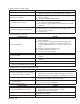
VII. TROUBLE SHOOTING GUIDE
Possible Cause Remedy
A. No air supply.
A1. Check to see if air is available at airset.
A2. Check to see if airset fi lter and/or dripwell is plugged.
B. Improper action; port "A" or "B"
connections reversed.
B. Reference Tables 1 & 2 herein for desired action and proper
port; reverse as required.
C. Check process isolation valve and line to
see if open and/or clear.
C1. Open block needle valve on process.
C2. Disconnect piping/tubing at both ends, blow to determine
if obstructed. Carefully blow needle valve to clear obstruction;
use caution commensurate with fl uid handled in accordance
with Owner's procedures.
D. Improper pressure tap location.
D. For relief applications, tapping is upstream; for reducing
applications tapping is downstream of the control valve.
E. PB needle valve is fully closed.
E. Open at east to alignment of matchmarks on valve's screw
head and housing.
F. Ice formation.
F. Use dry air as an IAS medium in cold weather. Thaw as
necessary by use of air heater. Trace as necessary.
G. Final element operation problem; i.e.
control valve, positioner, solenoid, etc.
G. Reference instructions for operation of fi nal element.
Possible Cause Remedy
A. Mismatch of pneumatic hardware.
A. Check bench set of actuator. Consider positioner or
booster.
B. Improper action; port "A" or "B"
connections are reversed.
B. Reference Tables 1 and 2 herin for desired action
and proper port; reverse as required.
1. No controller response
2. Improper control valve action.
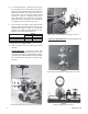
VI. SHOP CALIBRATION
1. Install a 1/4" pipe plug in the “OUTPUT” port of
unit.
2. Provide an 18 psig (1.2 Barg) IAS to the proper
port as determined by Table 1, Section II.
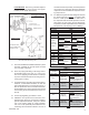
3. Leave PB as set in Section V.C.13. If this set-
ting is unknown, rotate the PB needle valve (3)
CW until seated. Rotate needed valve (3) CCW
until “indented matchmarks” align; this is ap prox i-
mate ly1/8–1/4 of a revolution.
4.1. Provide a known pressure (compressed nitrogen,
etc.) equal to the desired setpoint to the di a phragm
“PRO CESS” connection for the 764P.
4.2. For the 764PD, place a known static pressure
equal to the desired differential pressure setpoint to
the “HIGH” process connection; leave the “LOW”
process connection vented to at mo sphere.
5.1. FOR DIRECT ACTION: If the output pressure
gauge is at/near 15 psig (1.03 Barg) increase the
setpoint by rotating the adjusting screw (2.3) CW
until the output decreases to 9 psig (0.62 Barg)
If the output pressure gauge is at/near 0 psig
(0.0 Barg) decrease the setpoint by rotating the
ad just ing screw (2.3) CCW until the output rises
to 9 psig (0.62 Barg).
5.2 FOR REVERSE ACTION: If the output pressure
gauge is at/near 15 psig (1.03 Barg) decrease
the setpoint by rotating the adjusting screw (2.3)
CCW until the output decreases to 9 psig (0.62
Barg).
If the output pressure gauge is at/near 0 psig
(0.0 Barg) increase the setpoint by rotating the
ad just ing screw (2.3) CW until the output rises
to 9 psig (0.62 Barg).
NOTE: If the unit cannot be shop calibrated to either
the upper or lower value of the stated range, refer
to statement in VII.7.A. for recommendation. Re peat
shop calibration.