
Manual


I. DESCRIPTION AND SCOPE
The Model BQ is a back pressure relief regulator used to control upstream (inlet or P
1
) pressure. Side inlet and fl ow-thru
connections are 1/4", 3/8", and 1/2" NPT (DN8, DN10, DN15); outlet (bottom discharge) connection is always 1/2" NPT (DN15).
With proper trim utilization, the unit is suitable for liquid, gaseous, or steam service. Refer to Technical Bulletin BQ-TB for design
conditions and selection rec om men da tions.
MODEL BQ
BACK PRESSURE / RELIEF REG U LA TOR
II. INSTALLATION
INSTALLATION, OPERATION & MAINTENANCE MANUAL (IOM)
IOM-BQ
12-13
6. Clean the piping of all foreign material including chips,
welding scale, oil, grease and dirt before installing the
regulator. Strainers are recommended.
7. In placing thread sealant on pipe ends prior to en-
gage ment, ensure that excess material is removed
and not allowed to enter the regulator upon startup.
8. Flow Direction: Install so the fl ow direction matches
the arrow cast on the body. Connect the inlet pressure
to the body side connection(s). Fluid will relieve out of
the bottom connection. The double inlet connections
are for in-line installation (plug one side connection if
in-line installation is not required).
9. Regulator may be installed in a vertical or horizontal
pipe. If it is a steam system, ensure the piping is properly
trapped and vented.
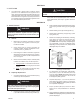
CAUTION
This is not a safety device and must not be substituted for a code approved pressure safety relief valve or a rupture disc.
SECTION II
SECTION I
WARNING
The maximum inlet pressure is equal to 1.5 times the larger
number of the stated range spring on the name plate, and is
the recommended “upper operative limit” for the sens ing
di a phragm. Higher pressures could damage the di a phragm.
(Field hy dro stat ic tests fre quent ly destroy di a phragms.
DO NOT HY DRO STAT IC TEST THRU AN IN STALLED UNIT;
ISOLATE FROM TEST.)
CAUTION
Installation of adequate overpressure pro tec tion is rec-
ommended to pro tect the reg u la tor from overpressure
and all down stream equip ment from damage in the event
of regulator failure.
1. An inlet block valve should always be installed.
2. If service application is continuous such that shutdown
is not readily accomplished, it is recommended that
an inlet block valve, outlet block valve, and a manual
bypass valve be installed.
3. Pipe unions should be installed to allow removal from
piping.
4. An inlet pressure gauge should be located ap prox i mate ly
ten pipe diameters upstream and within sight. An outlet
pressure gauge is optional.
5. All installations should include an upstream relief de vice
if the inlet pressure could exceed the pressure rating of
any equipment or the maximum inlet pres sure rating of
the unit.
CAUTION
For welded installations, all internal trim parts, seals and
diaphragm(s) must be removed from reg u la tor body prior to
welding into pipeline. The heat of fusion welding will dam-
age non-metallic parts if not re moved. NOTE: This does
not apply to units equipped with extended pipe nip ples.
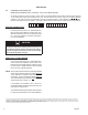
Recommended piping schematic for Back Pressure Regulator