
Manual


INSTALLATION, OPERATION & MAINTENANCE MANUAL (IOM)
IOM-DA0
11-13
I. DESCRIPTION AND SCOPE
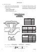
Model DA0 is a pressure reducing regulator used to control downstream (outlet or P2) pressure. Sizes are
1/2" (DN15), 3/4" (DN20), 1" (DN25), 1-1/4" (DN32), 1-1/2" (DN40), 2" (DN50), 3" (DN80) and 4" (DN100). Refer
to Technical Bulletin DA0-TB for design conditions and selection recommendations. (NOTE: This product was
formerly identifi ed as a Model D0; a Model DA0 and D0 are one and the same product.)
This manual does not include instructions related to the various methods of pressure loading a Model DA0
main valve.
MODEL DA0
DIRECT-ACTING, PRESSURE LOADED
PRESSURE REDUCING REGULATOR
for STEAM APPLICATIONS
II. REFERENCES
Refer to Technical Bulletin DA0-TB and DAG-TB
for tech ni cal specifi cations for this reg u la tor.
ABBREVIATIONS
CW – Clockwise
CCW – Counter Clockwise
ITA – Inner Trim Assembly
III. INSTALLATION
SECTION III
SECTION II
SECTION I
1. Regulator may be rotated around pipe axis 360
degrees. For ease of maintenance, the rec om-
mend ed position is with the cover dome (25)
up wards.
2. Provide space below, above, and around reg u la-
tor for removal of parts during maintenance.
3. Install block valves and pressure gauges to pro-
vide means for adjustment, operation, bypass,
or removal of the regulator. A pipeline strainer
is recommended before inlet to remove typical
pipe line debris from entering valve and damaging
internal “soft goods”, primarily the dynamic seal.
4. Steam traps should be installed before and after
the regulator to provide proper drainage.
5. Install the regulator with the fl ow in the direction
of the arrow cast or stamped into the body.
6. For best performance, recommend that the pip-
ing upstream and downstream of the regulator
be straignt and free from any restrictions, bend,
etd. which can cause turbulence, for a minimun
length of approximately fi fteen to twenty pipe
diameters.
7. Pipe size should be given special consideration,
particularly downstream of the regulator, to
ensure that the steam velocity does not exceed
industry or customer guidelines. Reference
DAG-TB, Table DAG-11 for rec om men da tions
for applying external pressure sensing.
8. External sensing, uses an external control line.
This line is connected from the 1/4" (DN8) NPT
tap on the side of the pilot body to a pressure
tap down stream of the regulator. Use 1/4" or
3/8" (DN8 or 10) outer di am e ter tubing or 3/8"
(DN10) pipe having an inner di am e ter equiv a lent
to Schedule 40 pipe. For condensable vapors (i.e.
steam) slope the external sensing line downward
2 to 5 de grees to outlet piping to prevent water
pock ets, which allows the diaphragm chamber
to always be self draining.
CAUTION
Installation of adequate overpressure pro tec tion is recom-
mended to pro tect the reg u la tor from overpressure and
all down stream equip ment from damage in the event of
regulator failure.