
Manual


IOM-DA0
3
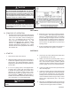
9. Develop system fl ow to a level near its expected
normal rate, and reset the regulator set point by
adjusting the loading system pressure control
setpoint to the desired outlet pressure level.
SECTION VI
10. Reduce system fl ow to a minimum level and
observe pressure set point. Outlet pressure
will rise from the set point of Step 9 for a Model
DA0. The max i mum rise in outlet pres sure on
de creas ing fl ow should not exceed the 10%. If
it does, consult factory.
VI. SHUTDOWN
1. Shutoff inlet block valve.
2. Shutoff auxiliary loading pressure source, if sup-
plied. For spring loaded pilots, relax the range
spring by turning the adjusting screw CCW until
adjusting screw is removed.
3. Allow suffi cient time for the line pressure down-
stream of the inlet block valve to bleed down.
4. Shutoff the outlet block valve.
5. Relieve the trapped upstream and downstream
pressure and loading pres sure.
6. The regulator may now be removed from the
pipe line or disassembled for inspection and pre-
ven ta tive main te nance while in-line.
VII. MAINTENANCE
A. General:
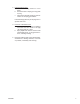
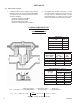
Item No. Part Description
7 ...................................................................................Nut
10 ......................................................................Stop Plate
13 ....................................................Guide Bearing/Piston
14 ...............................Lower and Upper Static Stem Seal
15 ..........................................................Cage O-ring Seal
16 ............................................................................ Wiper
17 ............................................................... Wiper Washer
19 ............................................................................. Cage
20 .............................................................................. Plug
21 ...................................................................... Seat Ring
27 ....................................................... Dynamic Side Seal
SECTION VII
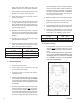
1. The regulator may be serviced without
re mov ing the regulator from pipeline. The
reg u la tor is designed with quick-change trim
to simplify maintenance.
2. Record the nameplate information to req-
ui si tion repair parts for the regulator. The
in for ma tion should include: size, Product
Code and Serial Number.
3. Refer to Section X for recommended repair
parts. Only use original equipment parts
sup plied by Cashco/KM for re build ing or
re pair ing reg u la tors.
4. Owner should refer to owner's procedures
for removal, handling, cleaning and disposal
of nonreuseable parts, i.e. gaskets, etc.
5. The Inner Trim is re moved and replaced in
the body ( 23) as an assemblage of parts.
The Inner Trim Assembly, here in af ter called
ITA, consists of the following parts:
WARNING
SYSTEM UNDER PRESSURE. Prior to per form ing any
maintenance, isolate the reg u la tor from the system and
relieve all pressure. Failure to do so could result in per-
sonal injury.
Figure 1: Dynamic Side Seals