
Manual


IOM-48
20
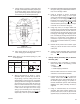
Benchset Higher Value Adder Loading
Range of Benchset Value – Pressure –
Range - “A” “B” “C”
_____ psig ____ psig 2 psig ____ psig
____ Barg ____ Barg .14 Barg ____ Barg
dial (15) such that travel in di ca tor (16)
shows “0°” travel before fully tightening
screws (31).
w. Completion to this point completes the
benchset range adjustment. Proceed
to Subsection VI.C. to adjust 90° travel
stop.
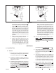
6. Units with ATC-FO (Direct) Action:
a. Disconnect the lower L.H. rod end (9)
from en gage ment with the lever arms (5)
by removing shoulder bolt (40) and lock
nut (46).
b. Swing the lever arms (5) down and as
close as possible to the travel stop screw
(35); this “closes” valve plug (6) / disc
(3.1). Ensure that the “closed” position
is reached by observing actual plug (6) /
disc (3.1) position.
c. Loosen lower upstop jam nut (43) from
securing upstop washer (54); back nut
(43) to the root of its threads on push rod
(10).
d. The upper R.H. rod end (8), lower L.H. rod
end (9), and push rod (10) act to geth er as
a turnbuckle; the upper end is stan dard
right-hand thread ed while the low er end is
left-hand thread ed. To ensure max i mum
and equal en gage ment of rod ends (8,9) to
the push rod (10), it is rec om mend ed that
the link age (8,9,10) be fully en gaged and
then re ad just ed as a safety pre cau tion.
Unequal engagement adjustment of rod ends (8,9) and
push rod (10) can cause failure of a rod end (8,9)-to-
push rod (10) connection.
a. If this occurs during bench maintenance, the
parts (8,9,10) could snap apart and cause
per son al injury.
b. If this occurs during installed operation, con trol
func tion would be lost.
e. Loosen lower L.H. rod end (9) jam nut (44)
by rotating CW (viewed from above); this
nut (44) is “left-handed”. Back nut (44) to
the root of its threads on push rod (10).
f. Using a suitable tool to prevent lower L.H.
rod end (9) from rotating, rotate push rod
(10) CCW (viewed from above) until up per
end of push rod (10) is fully en gaged with
upper R.H. rod end (8). NOTE: If lower L.H.
rod end (9) reaches full en gage ment with
lower push rod (10) end fi rst, remove tool
se cur ing against ro ta tion, and allow lower
L.H. rod end (9) to rotate with push rod
(10). Once upper end of push rod (10) is
fully en gaged with upper R.H. rod end (8),
rotate lower L.H. rod end (9) CW (viewed
from above) until it is fully en gaged.
g. Provide a temporary air supply with an
inline ad just able airset to the actuator
up per casing (1) connection.
h. Reference the nameplate (21) at tached
to the cover plate (20) that is fastened to
the arm housing (4). De ter mine the bench
setting from the nameplate (21).
i. Rotate lower L.H. rod end (9) until the rod
end (9) and the lever arm’s (5) holes are
in the same plane.
j. Loosen jam nut (45) and rotate downtra-
vel stop screw (35) out by ro tat ing CCW
(viewed from below screw’s (35) head)
until just barely engaged in arm hous ing
(4).
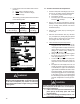
k. Pressurize actuator (AA) to the higher
value of the benchset range pressure
in di cat ed on the nameplate (21), while
“guid ing” the lower L.H. rod end (9) hub
to its proper position between the lever
arms (5).
l. Pressurize actuator (AA) to a level as
indicated by “C” pressure in table that
follows according to the formula: “A” +
“B” = “C”.
CAUTION
m. Adjust the push rod (10) by rotating CW
(viewed from above) until the holes of the
lever arms (5) and the lower L.H. rod end
(9) are centered and the valve is in the
“closed” position.
n. Reinstall the shoulder bolt (40) through
the lever arm (5) and lower L.H. rod end
(9) holes. Finger-tighten lock nut (46) onto
shoulder bolt (40). Using a 1/4" allen key
wrench to secure the head of shoul der
bolt (40), torque wrench-tighten nut (46)
to 15-20 ft-lbs (20-27 N-m).
o. Loosen double jam nuts (43,43) on top
side of uptravel stop washer (54).
p. With valve in “closed” position, reinstall
bearing (18), bearing fl anges (19), cov-
erplate (13), dial lens (14) and dial (15)
with three cap screws (31). NOTE: Po-
si tion dial (15) such that travel in di ca tor