INSTALLATION, OPERATION & MAINTENANCE MANUAL (IOM) IOM-148 12-13 MODEL 148 SPRING/DIAPHRAGM ROTARY ACTUATOR SECTION I I. DESCRIPTION AND SCOPE Models 148D and 148R are multi-spring, single acting, spring opposed, rotary actuators used with Cashco rotary control valves. Regardless of final installed failure action, the actuator is always pressurized on “top” of the traveling diaphragm plate.
TABLE 1 ACTUATOR MODEL NO. vs. VALVE BODY MODEL (Model 48 included for clarity) Full Actuator Model No. Available Bench Settings Basic Modifier Actuator psig Number Model No. 48R or -01 5-15 48D 148R or -01 5-13 148D 148R or -02 10-26 148D 148R 7.5or -03 19.5 148D * Metric body size in parenthesis. Air Supply Pressure Unitized Products* (Barg) psig (Barg) (.34-1.03) 20 (1.4) (.34-0.90) 20 (1.4) (.69-1.79) 36 (2.5) 4”-8” (DN100-200) Ranger QCT, 10” (DN250) Premier EZO (.52-1.34) 27 (1.
Position A Position A Position B Position B FIGURE 4: Mounting position of Premier EZO or Premier Unlined to Model 148 Actuator with Model 73N-B P/P Positioner. FIGURE 5: Mounting position of Premier EZO or Premier Unlined to Model 148 Actuator with Models 9540R P/P or Smart Positioner’s PS2 and 991. 3. A 1/4"–NPT female connection for pneumatic LOAD is located on the side of the actuator’s upper diaphragm casing near the casing flange joint.
TABLE 2 RANGER QCT ACTUATOR BENCHSET RANGES Valve Body Size in. (DN) 1”, 1-1/2” & 2” (25, 40 & 50) 3” & 4” (80 & 100) 4”, 6’ & 8” (100, 150, & 200) Actuator Model No.* Failure Action 48R-01 ATO-FC 48D-01 ATC-FO 148R-01 ATO-FC 148D-01 ATC-FO 148R-02 ATO-FC 148D-02 ATC-FO Benchset Range Supply Pressure Qty of Range psig (Barg) psig (Barg) Springs 5-15 (.34-1.03) 20 (1.4) 6 5-13 (.34-.90) 20 (1.4) 4 10-26 (.69-1.79) 36 (2.
SECTION V V. MAINTENANCE A. General: 1. Hereafter, all maintenance, disassembly, etc., is assumed to be done in an indoor shop. 2. Most actuators are a sub-assembly that is unitized with a body sub-assembly. Reference should be made to the IOM for the correct body utilized. 3. Where the body is not being disassembled, special care MUST be exhibited to prevent valve stem rotation during any disassembly or reassembly for all types of valves. Following this procedure will ensure not damaging seating surfaces.
4. For ATO-FC valve action, it is necessary to remove “stem windup” - use either a. or b. a. Rotate manual handwheel operator (MHWO) handwheel (58.1) approximately 1-3 revolutions CW (viewed from above handwheel) until interconnecting arm and stem linkage (5, 10) of actuator “relax”. b. Pressurize actuator casing (1) only until the interconnecting arm and stem linkage (5,10) “relax”. DO NOT OVERPRESSURIZE. NOTE: Do not remove the drive coupling ((32)) unless required. 5.
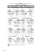
FIGURE 6: ORIENTATION – RANGER QCT ACTUATOR MOUNTING POSITIONS WITH MODEL 73 P/P POSITIONER REVERSE ACTION NOTES: IOM-148 DIRECT ACTION 1. Flangeless valve design indicated; integral flanged units follow same orientation. 2. Dimension tables are included in the Ranger-TB.
FIGURE 7: ORIENTATION – RANGER QCT/PREMIER ACTUATOR MOUNTING POSITIONS WITH MODELS 9540R P/P or 991 or PS2 I/P POSITIONERS REVERSE ACTION NOTES: 8 DIRECT ACTION 1. Flangeless valve design indicated; integral flanged units follow same orientation. 2. Dimension tables are printed in the Ranger-TB.
FIGURE 8 PREMIER ACTUATOR MOUNTING POSITIONS – 73 Position "A" is standard for fail closed action. Position "B" is standard for fail open action. Position "C" and "D" covers vertical piping. FIGURE 9 PREMIER ACTUATOR MOUNTING POSITIONS – 9540R/991/PS2 Position "A" is standard for fail closed action. Position "B" is standard for fail open action. Position "C" and "D" covers vertical piping.
. Reorient body assembly (BA) with respect to the actuator assembly (AA). Rejoin the body assembly (BA) to the actuator assembly (AA) as described in this section, V.I. Ensure proper plug (Ranger (6)) or disc (Premier (3.1)) position prior to reinstalling lever arms (5). Ensure that the lever arms (5) are “centered” within the arm housing (4), and with respect to the actuator stem linkage (8) (9) (10) (43) (44). 11. Recalibrate the unit (AA) (BA) and its positioner ((PA)). D. Changing Failsafe Action: 4.
CCW-TO-OPEN ATC-FO (DIRECT) Push Down-to-Close CCW-TO-OPEN ATO-FC (REVERSE) Push Down-to-Open NOTE: To switch “action” requires locating actuator stem to opposite side of valve stem. Figure 10 Ranger Plug vs. Lever Arm vs. Actuator Orientation LOAD LOAD VENT VENT OPEN Rotation CLOSE CCW-TO-OPEN ATC-FO (DIRECT) Push Down-to-Close OPEN Rotation CLOSE CCW-TO-OPEN ATO-FC (REVERSE) Push Down-to-Open NOTE: To switch “action” requires locating actuator stem to opposite side of valve stem.
15. Place a light coating of graphite powder lubricant, Dow-Corning “Molycote” (dry molybdenum disulfide) or equal, on the skirted areas of diaphragm (6), and into the “valley”. This lubricant will prevent the diaphragm (6) from “sticking together” or abrading itself during piston (3) travel. 16. If actuator (AA) is supplied with a manual handwheel operator (MHWO), place a heavy-duty wheel bearing grease, Lubriplate No. 130-AA, or equal, into the v-notch in the head of the pivot screw (25). 17.
gland (67) and rotate CCW (viewed from above) to removal of the manual handwheel operator sub-assembly (MHWO). 6. Place the sub-assembly (MHWO) into a vise, grasping with leaded jaws on the coarsescrewed handwheel stem (58.2) near the base of the handwheel (58.1), oriented to allow driving-out the rolled pin (66) securing the handwheel (58.1) to the handwheel stem (58.2). 7. Drive pin (66) out using a suitable punch and locking pliers. Set pin (66) aside for reuse. Remove handwheel (58.1) from stem (58.2).
8. Remove all range springs (11) and set in a row side-by-side. Inspect for any difference in the spring (11) height or verticality. Replace any abnormal spring(s) (11). Replace any springs (11) that show cracks, nicks, damaged epoxy coating, corrosion, etc. Inspect springs (11) using data in table below as the “normal”: tially a complete actuator (AA) disassembly. It is recommended that the range spring (11) replacement should include: a. diaphragm (6) replacement b. O-ring(s) (62) (63) replacement c.
Benchset Range psig (Barg) Quantity of Springs Array Hub w/NO Spring (11) 5-13 (0.34-0.90) 4 Hub With Spring (11) Hub w/NO Spring (11) 7.5-19.5 10-26 (0.52-1.34) (0.69-1.79) 6 8 Hub With Spring (11) Spring (11) on ALL eight hubs 11. Aligning matchmarks of Article 7. above, reposition piston (3) back onto top side of range spring (11) array.
at least one bolt hole of the yoke (12) with one bolt hole in the arm housing (4). Insert one cap screw (24) from behind the yoke’s (12) bolt hole and engage with the tapped opening in the arm housing (4); finger tighten cap screw (24). 8. Reposition actuator assembly (AA) as required to align the three remaining bolt holes securing yoke (12) with arm housing (4). Insert the three cap screws (24) and finger-tighten. 9. Use cardboard, or some tool that can provide approximately 1/32" (0.
CLOSED LOAD LOAD VENT VENT OPEN OPEN OPEN CLOSED CLOSED CLOSED ATC-FO (Direct) Action ATO-FC (Reverse) Action Figure 13: key wrench until firmly tight. NOTE: Ensure that cover plate (13) is shouldered properly into position on back side. 20A. Units (AA, BA) with Model 73N-B or without positioner: a. Insert rolled spring pin (51) into indicator spacer (17). Pin (51) will protrude approximately 1/16" (1.5 mm). b. Position travel indicator (16) onto end of shaft (Ranger (7), Premier (3.
SECTION VI VI. CALIBRATION A. General: 1. This section covers calibration of the actuator assembly (AA) to a Ranger QCT, Premier EZO, or Premier Unlined body assembly (BA). 2. Positioner, if installed, requires reference to the specific positioner model IOM for proper calibration procedure. 3. All indicated Item Numbers that are with respect to this Model 148 actuator assembly (AA) are in parenthesis but are not underscored; i.e. (20).
CAUTION Unequal engagement adjustment of rod ends (8,9) and push rod (10) can cause failure of a rod end (8,9)-to-push rod (10) connection. a. If this occurs during bench maintenance, the parts (8,9,10) could snap apart and cause personal injury. b. If this occurs during installed operation, control function would be lost. e. Loosen lower L.H. rod end (9) jam nut (44) by rotating CW (viewed from above); this nut (44) is “left-handed”. Back nut (44) to the root of its threads on push rod (10). f.
value), the length of the actuator stem sub-assembly (8, 9, 10, 43, 43, 43, 44, 54) must be shortened. Repeat procedure from Article 5.a. through to this Article. If movement is late (i.e. movement at more than the lower benchset range value), the length of the actuator stem sub-assembly (8,9,10,43,43,43,44,54) must be lengthened (i.e. increased). Repeat procedure from Article 5.a. through to this Article.
Higher Value of Benchset Range - “A” Adder Value “B” Loading Pressure - “C” _ psig _ psig 2 psig _ psig _ Barg _ Barg .14 Barg _Barg Adjust the push rod (10) by rotating CW (viewed from above) until the holes of the lever arms (5) and the lower L.H. rod end (9) are centered and the valve is in the “closed” position. Reinstall the shoulder bolt (40) through the lever arm (5) and lower L.H. rod end (9) holes. Finger-tighten lock nut (46) onto shoulder bolt (40).
Product Model Gap Between L.H. Rod End (9) and Downtravel Stop Screw (35) Ranger QCT 1/8” ± 1/16” (3.0 mm ± 1.5 mm) Premier EZO 1/16” ± 1/16” (1.5 mm ± 1.5 mm) Premier Unlined No gap; i.e. touching SECTION VII VII. TROUBLE SHOOTING GUIDE Reference the IOM of the valve body which this actuator is unitized with for additional information on Trouble Shooting. 1. Air leakage. Possible Causes Remedies A. Leakage at diaphragm-to-upper casing flange. A1. Overpressure.
58.1 66 60 61 59 62 67 65 25 56 64 63 47 52 6 60 58.2 58.2 61 59 26 67 65 62 1 ADJUSTING SCREW ASSEMBLY Not availabe on Air to Close-Fail Open Rangers 3 48 7 49 8 1/4" (DN8) NPT 27 28 42 41 R.H. THREAD 11 A 43 2 L.H. THREAD 10 9 22 20 38 36 ACTUATOR PLUG Available on Premier Butterfly Valves ONLY 33 5 50 12 45 A 35 DESCRIPTION ITEM NO. Upper Case 38. Lower Case 39. Piston 40. Arm Housing 41. Arm 42. Diaphragm 43. Clevis 44. Rod End (R.H.) 45. Rod End (L.H.) 46.
106 107 72 72 A 35 1/4" NPT 1/4" NPT Signal Supply 35 101 12 108 A VENT POSITIONER Air-To-Open SECTION A-A 35 OUTPUT 106 VENT 102 STOP SCREW 131 1/4" NPT Supply 128 129 1/4" NPT Inlet 130 ACTUATOR SOLENOID VALVE 73N-B POSITIONER ITEM NO. DESCRIPTION 72 Feedback Linkage Subassembly 73 Feedback Linkage Spacer 74 Feedback Linkage Pivot Shaft 101 Positioner 102 Range Spring 106 Tube Fitting (Elbow) 107 Output Tube 108 Name Plate SOLENOID VALVE ITEM NO.