
User guide
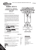


IOM-SCV-S
8
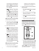
(16) to the "C" mark on the in di ca tor plate
(23), mak ing sure to use the “top edge” of the
in di ca ting washer (16) as the ref er ence point.
Adjust indicator plate as needed.
10. Slowly increase the pressure in the actuator
until the indicating washer (16) is in alignment
with the "O" mark on the indicator plate.
11. To limit the up travel at the desired stroke
length, rotate the travel stop nut (52) CW and
secure to bottom of attachment hub (4).
NOTE: Secure the actuator stem (6) by the
fl ats when rotating the travel stop nut.
NOTE: "Stroke" length is indicated on the
nameplate (40), and is the distance between
the "C" and "O" marks of the indicator plate
(23).
NOTE: The proper calibration of the actuator
/ valve unit will occur when at the lower pres-
sure level of bench setting, the valve plug (3)
will just begin to travel from the "C" position.
At the upper level of the bench setting, the
actuator pressure should be within ±8% of
the upper bench range for the desired stroke
length.
12. Release all pressure from actuator.
C. Procedure - Direct Action, ATC-FO:
1. Reference the nameplate (40) attached to
the actuator yoke (3). Determine the bench
set ting of the installed range springs (10) from
the nameplate (40).
2. Connect a temporary air supply with an in-line
ad just able airset regulator and gauge to the
upper actuator con nec tion. DO NOT LOAD
with any air pressure at this point.
3. To determine when stem/plug (3) makes
contact with the seat and travel stops, touch
the stem with one fi nger. (Stem movement
will stop when the plug engages the seat.)
4. Slowly pressurize the ac tu a tor to a pres sure
equal to the upper pres sure lev el of the bench-
setting; i.e. for a 5-15 psig (.34 -1.0 Barg)
range, set pressure at 15 psig (1.0 Barg).
Take note of the pressure reading when stem
travel actually stops.
5. If the loading pressure, when stem movement
stops, is below the upper end of the desired
bench setting, then the com bined stem (3,10,
& 6) length is too long.
For Std Threaded Stem:
a. Rotate both jam nuts (17) down to base of
threads on stem (3) and tighten together.
b. Decrease pressure in the actuator to
approximately mid range of the bench
setting.
c. Rotate lower jam nut CCW to shorten the
combined stem length. DO NOT allow
actuator stem (6) to rotate in the actuator.
d. Rotate upper jam nut CW to hold indicat-
ing washer (16) up against stem (6).
e. Release all pressure from the actuator
and repeat Step 4 previous.
For Opt-68 QDS Stem:
a. Rotate jam nuts (17) down to base of
threads on upper coupling (42a).
b. Decrease pressure in the actuator to
approximately mid range of the bench
setting.
c. Rotate upper coupling (42a) CW to shorten
the combined stem length. DO NOT allow
actuator stem (6) to rotate in the actuator.
d. Rotate upper jam nut CW to hold indicator
washer (16) up against stem (6).
e. Release all pressure from the actuator
and repeat Step 4 previous.
6. If the loading pressure, when stem movement
stops, is above the upper end of the desired
bench setting, then the com bined stem (3,10
& 6) length is too short.
For Std Threaded Stem:
a. Rotate both jam nuts (17) down to base of
threads on stem (3) and tighten together.
b. Decrease pressure in the actuator to
approximately mid range of the bench
setting.
c. Rotate upper jam nut CW to increase the
combined stem length. DO NOT allow
actuator stem (6) to rotate in the actuator.
d. Rotate upper jam nut CCW to hold indicat-
ing washer (16) up against stem (6).
e. Release all pressure from the actuator
and repeat Step 4 previous.
For Opt-68 QDS Stem:
a. Rotate jam nuts (17) down to base of
threads on upper coupling (42a).
b. Decrease pressure in the actuator to
approximately mid range of the bench
setting.
c. Rotate upper coupling (42a) CCW to
increase the combined stem length. DO
NOT allow actuator stem (6) to rotate in
the actuator.