E Handheld Terminal Series User’s Guide Be sure to read “Safety Precautions” inside this guide before trying to use your Handheld Terminal.
Contents Safety Precautions ........................................................................................E-3 Operating Precautions ..................................................................................E-8 Important ........................................................................................................E-8 After Service ........................................................................................................ E-8 Regulatory Information ....................
Handling microSD Cards ............................................................................E-37 Installing............................................................................................................. E-37 Removing ........................................................................................................... E-38 Handling SIM Cards .....................................................................................E-39 Installing..........................................
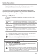
Safety Precautions Congratulations upon your selection of this CASIO product. Be sure to read the following Safety Precautions before trying to use it for the first time. Your neglect or avoidance of the warning and caution statements in the subsequent pages causes the danger of fire, electric shock, malfunction and damage on the goods as well as personal injury. Markings and Symbols The following are the meanings of the markings and symbols used in these Safety Precautions.
Warning Dust and Moisture • Though the Handheld Terminal is dust and water splash resistant, its options including the battery pack are not. Keep loose metal objects and containers filled with liquid away from your Handheld Terminal and the options. Also, never handle the Handheld Terminal and the options while your hands are wet. Laser Light • The laser scanner models (model dependant) with the integrated laser scanning module scan bar codes using laser light.
Caution Foreign Objects • Take care to ensure that metals or combustible objects are not inserted into the openings of the Handheld Terminal or its options, and not to allow moisture to get inside of them. Location • Install the cradle properly on a flat and stable surface so that it cannot fall down onto floor. LCD Screen • Never apply strong pressure to the screen or subject it to strong impact. Doing so can crack the LCD Screen.
Optional Lithium-ion Battery Pack Danger • Never use the Handheld Terminal and its option including the battery pack and battery next to open flame, near a stove, or any other area exposed to high heat, or leave them for a long period of time in a vehicle parked in direct sunlight. • Never use the battery pack with any device other than the Handheld Terminal. • Never dispose of the battery pack by incinerating it or otherwise expose it to heat.
Power Supply / AC Adaptor Warning • Do not use the Handheld Terminal at a voltage other than the specified voltage. Also, do not connect the Handheld Terminal to a multi-plug power strip. • Never modify, sharply bend, twist, or pull on the power cord. • Never use a detergent to clean AC adaptor and its power cable, especially on the plug and the jack. • When using the battery chargers and the cradles, be sure to use the respective AC adaptors. Caution • Never pull on the power cord when unplugging it.
Operating Precautions Your Handheld Terminal and its options are precision. Improper operation or rough handling can cause problems with data storage and other problems. Note and observe the following precautions to ensure proper operation. • Do not leave dead battery pack in the Handheld Terminal for a long period. Dead battery pack can leak, leading to malfunction and damage to the Handheld Terminal.
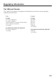
Regulatory Information The USA and Canada The CASIO IT-800 models are designed, tested and found to meet the relevant regulatory standards described below.
GUIDELINES LAID DOWN BY FCC RULES FOR USE OF THIS UNIT IN THE U.S.A. (not applicable to other areas). NOTICE This equipment has been tested and found to comply with the limits for a Class B digital device, pursuant to Part 15 of the FCC Rules. These limits are designed to provide reasonable protection against harmful interference in a residential installation.
L’ utilisation de ce dispositif est autorisée seulement aux conditions suivantes : (1) il ne doit pas produire de brouillage et (2) I’ utilisateur du dispositif doit étre prêt à accepter tout brouillage radioélectrique reçu, même si ce brouillage est susceptible de compromettre le fonctionnement du dispositif.
DECLARATION OF CONFORMITY We, the under signed, CASIO Europe GmbH, hereby declare that the following types of the product: Product: Handheld Terminal Type: IT-800R, IT-800RG Brand: CASIO are in conformity with all the provisions of the EC directive bellow meeting with the relevant standards: Council Directive: 1999/5/EC (R&TTE Directive): Standards applied to all the types: EN 300 328 v1.7.1 (2006-10) EN 60950-1: 2006 EN 300 330-2 v1.3.1 (2006-04) EN 50364: 2001 EN 301 489-3 v1.4.
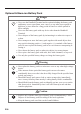
Checking in the Box Please check the contents of the box before using the Handheld Terminal for the first time. Open the box and make sure that all the items shown here are included. Handheld Terminal Neck Strap Stylus The stylus can be attached to the hand belt. The hand belt is attached on the back of the terminal. Set the hand belt in proper length by adjusting the hook-loop fastener prior to using the terminal. The stylus string can be attached to the stylus and hand belt.
Handheld Terminal System Configuration Options The illustration shows the USB Cradle (HA-H60IO). USB Cradle HA-H60IO IT-800 Series Ethernet Cradle HA-H62IO Cradle-type Battery Charger HA-H30CHG Car Mounted-type Battery Charger HA-H35CHG IT-800EC-05 IT-800EC-35 These models are available in the USA and Canada only. The car power cable accompanies to HA-H35CHG. For the latest options list, refer to the ON-LINE manual available at http://world.casio.com/system/pa/UsersGuide/sup85_e.
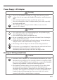
Options Battery Pack HA-D20BAT/HA-D20BAT-A (Battery Pack) Dual Battery Charger HA-D32DCHG HA-D21LBAT/HA-D21LBAT-A (Large-capacity Battery Pack) For WWAN models*, be sure to use either HA-D20BAT-A or HA-D21LBAT-A battery pack.
General Guide Top 19 19 IT-800R-15 IT-800RC-15 19 IT-800RGC-15 IT-800R-35 IT-800A-35 IT-800EC-35 IT-800RC-35 19 IT-800R-05 IT-800EC-05 IT-800RGC-35 IT-800RGC-05 Left 25 25 17 17 18 18 20 19 19 Front 1 23 4 Right 5 6 20 7 7 8 13 9 10 11 15 12 14 Back Bottom 33 34 21 23 24 26 32 31 30 29 E-16 27 28 22 25 25 16 16
1 2 Receiver Indicator 1 3 Indicator 2 4 5 Power Key Screen* 6 Center Trigger Key Center Key (for IT-800R-05/EC-05/ RGC-05) Function Keys Used when starting a pre-registered application. Enter Key Press when finishing entering numerical values or when moving to the next step. Mode Key The key switches the character input mode, either characters in lowercase letter or characters in uppercase letter.
18 DC Jack 19 Barcode Reader SD Card Slot (for IT-800R-05/EC-05/ RGC-05) IR Port Power/Signal Terminals Strap Holes Camera Lens (Camera models) LED (Camera models) Car Mounted-type Battery Charger Mount Holes Reset Switch microSD Card Slot (for IT-800R-15/RC-15/ RGC-15/R-35/A-35/ RC-35/RGC-35/EC-05) Battery Pack Cover 20 21 22 23 24 25 26 27 28 29 Cradle Mount Holes 30 SIM Card Slot (for IT-800RGC-05/ RGC-15/RGC-35) 31 Battery Pack Cover Lock Switches 32 Extension Port 33 Stylus 34 Hand Belt The dedica
Loading and Removing the Battery Pack Your Handheld Terminal uses two types of battery: a battery pack and a memory backup battery. The battery pack is used to power normal operations and to store data, while the memory backup battery provides the power required to maintain memory contents when the battery pack power is unable to supply power for some reason. You can choose either battery pack (HA-D20BAT, HA-D20BAT-A) or large-capacity battery pack (HA-D21LBAT, HA-D21LBAT-A) for operating power.
Loading .1 %- (4 '' 1. Turn the terminal upside down and loosen the hand belt. .1 %- (4 '' (4 '' .1 %- 2. Slide the left and right lock switches for the battery pack cover to the “FREE” position, and then remove the battery pack cover. .1 %- (4 '' (4 '' .1 %- 3. Load a battery pack (HA-D20BAT, HA-D20BAT-A) or large-capacity battery pack (HA-D21LBAT, HA-D21LBAT-A). Take care that the battery pack is oriented correctly when you load it.
Removing 1. Make sure that the Handheld Terminal is turned off. If the power is on, press the power key to turn it off. 2. Turn the terminal upside down and loosen the hand belt. 3. Refer to “Loading” on the previous page and remove the battery pack cover. 4. Remove the battery pack by pulling up the removal tape as shown in the illustration.
Charging the Battery Pack Battery pack installed in the terminal can be charged using either cradle, battery charger or AC adaptor (AD-S15050B). Battery charge condition can be monitored with Indicator 1 on the terminal. Multiple battery packs can also be charged simultaneously using Dual Battery Charger.
Dual Battery Charger Taking care that the battery pack is oriented correctly, insert it into the Dual Battery Charger. This causes the Charge Indicator LED to light in red, indicating that charging has started. AD-S42120C-N5 AD-S42120B You can connect up to three Dual Battery Chargers.
Handling the Hand Belt The hand belt is attached to the terminal. Remove it if it is not necessary. To remove the hand belt 1. As shown in the figure, pull out the metal part of the hook while pressing down the protrude part that has a small dimple on it. 2. Loose the hook-loop fastener and then pull out the belt through the hand belt hook as shown in the figure. To attach the hand belt 1. Thread one end of the hand belt through the hand belt hook.
Connecting the Stylus String The string can be connected to stylus and hand belt to prevent loss of stylus or misplacing. Follow the instruction below to connect it to stylus and hand belt. 1. Thread one end of the string through the slit on stylus as shown in the illustration. 2. Thread the other end of the string through the loop as shown in the illustration, and then pull the other end to tighten. 3.
Attaching the Neck Strap The neck strap can be used to prevent the Handheld Terminal from fall when carrying it around. Since there are two strap holes where the neck strap can be attached, use the hole that affords the ease of use. Attach the neck strap according to the procedure described below. To attach the neck strap 1. Pass the thin cord of the neck strap through the strap hole on the back of the Handheld Terminal. 2.
Configuring Handheld Terminal Settings Calibrating Touch Screen Alignment Whenever the response of the touch screen is poor, or operation being executed does not match with the location you are tapping on the touch screen, please recalibrate the alignment of the touch screen using the following method. • Press the “Fn” key and then press the “4” key after confirming that “F” is displayed in the lower right corner of the screen. The following screen is displayed.
Adjusting Display Brightness You can use the following procedures to adjust display brightness to make it easier to read under different lighting conditions. • Press the “Fn” key and then press the “5” key or “6” key after confirming that “F” is displayed in the lower right corner of the screen. Pressing the “5” key adjusts brightness for a darker display, while pressing the “6” key adjusts brightness for a lighter display.
Using the Laser Scanner (Laser Models) 1. After turning on the power, position the laser scanner close to a bar code and then press the trigger key. 2. The laser emits light and scans the bar code. If scanning is completed normally, Indicator 2 displays a green light. Important! • If you are unable to scan a bar code, try changing the angle at which the scanner is held or distance from the scanner to the bar code, and then try scanning again.
Using the C-MOS Imager (Imager Models) 1. Turn on the Handheld Terminal, position its C-MOS Imager reader port near the bar code or 2D code, and then press the trigger key. 2. The Handheld Terminal reads the code by emitting laser and red lights. Indicator 2 (read operation indicator lamp) lights in green when the reading is successful. Bar code and stacked 2D code Reading Guide When you press the trigger key, LEDs in the Handheld Terminal emit laser and red lights.
Adjusting the Laser Light Emission Width The emission width of the laser light emitted by the Handheld Terminal (model dependant) can be adjusted. Adjust the emission width when it is improper. 1. Navigate to the menus in the following sequence: Start Settings System The Control Panel appears as shown in the screen. 2. Tap the [Scanner Setting] icon. The Setting screen appears as shown in the screen. 3. Tap the [Others] tab in the Scanner Setting screen.
4. Tap the [Calibration] button. The display appears as shown at right. 5. Press the trigger key to emit laser light, and align the light with the barcode for adjusting emission width. • Align the laser light with the narrow bars on both sides. • The message appears as shown at right when adjustment is completed. • Repeat the setting if “Setting failed” message appears.
Handling the NFC The NFC is a technology of contactless IC card for short range communication that enables writing data to card and reading data from the card by applying the card close to the screen on IT-800. The integrated NFC can read a contactless IC card used typically for employment identification, etc. 1. Apply a card so that it is positioned in parallel with the screen.
Performing Communications IR Communication IR communication can be used to transfer data between two Handheld Terminals. When performing IR communication, orient the IR ports of both Handheld Terminals so they are pointing directly at each other. The ports can be in direct contact with each other, or they can be separated by up to 30cm (1113⁄16") (up to 20cm (7 7⁄8") for communication between units). Important! • A high sensitivity communication element is used during IR communication.
Bluetooth® Communication Bluetooth® interface can also be used to transfer data between two Handheld Terminals. With Bluetooth® the two Handheld Terminals should be located within about three meters (9'103⁄8") from each other, as long as there is nothing blocking the path between them. Important! Observe the following precautions to help ensure that Bluetooth communication is successful. • Make sure two Handheld Terminals face each other within three meters (9'103⁄8").
GSM/W-CDMA Communication To use the GSM/W-CDMA functions, you must receive service from a wireless service provider. Available GSM/W-CDMA functions may be dependent on the service provider to which you connect. Please consult your service provider for details about network service. If you use GSM/W-CDMA and WLAN at the same time, the communication speed of WLAN may be reduced, or the reception of WLAN signals may be disconnected, due to the operational state of GSM/W-CDMA.
Handling microSD Cards The Handheld Terminal supports microSD card. The employment of microSD card slot is dependent on model. See page 18 for the models with microSD card slot integrated. Since the microSD card slot is located inside the battery pack compartment, first remove the battery pack when installing or removing a microSD card. Refer to pages 19 to 21 for information on “Loading and Removing the Battery Pack”. Install (or remove) a microSD card according to the procedure described below.
Removing 1. Make sure that the power on the terminal has been switched off. If the power is still on, press the power key to switch off. 2. Remove the battery pack. 3. As shown in the figure, pull out the card while pressing down the small plastic spring plate. 4. Load the battery pack. Important! • A microSD card must be inserted with the top and bottom properly aligned and in the proper direction.
Handling SIM Cards The Handheld Terminal supports SIM card. The employment of SIM card slot is dependent on model. See page 18 for the models with SIM card slot integrated. Since the SIM card slot is located inside the battery pack compartment, first remove the battery pack when installing or removing a SIM card. Refer to pages 19 to 21 for information on “Loading and Removing the Battery Pack”. Install (or remove) a SIM card according to the procedure described below. Installing 1.
Removing 1. Make sure that the power on the terminal has been switched off. If the power is still on, press the power key to switch off. 2. Remove the battery pack. 3. Put your finger’s nail into the slit of the plastic holder, and then lift it up. See the figure below. 4. Pull the SIM card out of the slot by sliding it to the direction shown by the arrow. See the figure below. 5. Put back the plastic holder to its home position until you hear a click sound. 6. Load the battery pack.
Handling SD Memory Cards SD memory card can be installed in the SD memory card slot on the Handheld Terminal. The employment of SD memory card slot is dependent on model. See page 18 for the models with SD memory card slot integrated. Install (or remove) an SD memory card according to the procedure described below. Installing 1.
Resetting the Handheld Terminal Resetting the terminal is the same as resetting a PC. Performing a reset causes all unsaved RAM data to be lost that are in mid-course of inputting and editing, but data and settings that are already stored in the FlashROM should be unaffected. Perform a reset to restore normal operation whenever the Handheld Terminal operates abnormally due to misoperation or some other reason. Use a stylus to press the reset switch on the back of the IT-800. This starts the reset operation.
1. Hold down Fn key and CLR key while pushing down the reset switch for about 3 seconds with the tip of a stylus until the message shown below appears on the display. • To cancel the full reset operation, press L Trigger key on the scan engine integrated models or Up key on the non-scan engine integrated models. Message appeared on the scan engine integrated models. R Trigger key Message appeared on the non-scan engine integrated models. 2.
Warning Label Warning! ■ Never look directly into the laser light. • These products scan using laser light. Never look directly into the laser light or shine the laser light into the eyes. IT-800R-15/RC-15/RGC-15/ RGC-35 IT-800R-35/A-35/RC-35/ EC-35 • This label is a warning and caution label for Class 2 laser products that comply with IEC60825-1:2007. • Although Class 2 laser light is only emitted momentarily, never look directly into the beam light.
IT-800 Specifications Model: IT-800R-05/RGC-05/R-15/RC-15/RGC-15/R-35/RC-35/RGC-35/ EC-05/EC-35 CPU: Marvell® PXA320 624MHz Memory: 128MB RAM, 128MB Flash ROM (user defined: 80MB) OS: Microsoft® Windows Mobile® 6.1 operating system, English Version Display: 9.4 cm (3.
NFC: Frequency Band: 13.56 MHz ± 7 KHz Antenna: Magnetic Loop Antenna Operating Magnetic Field: Magnetic Length Output 1.
W-CDMA (IT-800RGC-05/RGC-15/RGC-35): Standard: UMTS/W-CDMA: 3GPP release 99 HSDPA: 3GPP release 5 Communication functions: Voice sound, circuit switching data, packet data Approx. 150 hours in continuous wait state for incoming call. Approx. 270 minutes for continuous call (with HA-D21LBAT) Data Transmission: Packet: 64 Kbps, 128 Kbps, 384 Kbps Category12 (1.8 Mbps) Category6 (3.6 Mbps) Category8 (7.
SIM card: Standard: ISO 7816 IC Card standard General specifications: Support for 3 V and 1.8 V SIM cards Camera (IT-800RGC-05/RC-15/RGC-15/RC-35/RGC-35/EC-05/EC-35): Approx. 2,000,000 pixels Autofocus function Power Requirements: Power Source: Battery Pack (HA-D20BAT, HA-D20BAT-A, HA-D21LBAT or HA-D21LBAT-A) Memory Backup: Rechargeable Lithium Battery (Built-in) Consumption Current: DC 2.3A : IT-800R-05/R-15/RC-15/R-35/RC-35/EC-05/EC-35 DC 3.
Using the USB Cradle (HA-H60IO) The optionally available USB Cradle (HA-H60IO) makes it possible to transmit system data and file data between the Handheld Terminal and a PC via a USB connection (download or upload). You can also use the USB Cradle to charge the battery pack installed in the Handheld Terminal.
1 USB Client Port This port is used to transmit system data and file data (download, upload) by connecting the Cradle to a PC using a USB cable (DT-380USB). A dedicated driver must be installed in the PC before connecting the Cradle to the PC. 2 USB Host Port This port is used to connect a corresponding USB peripheral device. 3 Selector Switch This switch is used to switch between the USB host port and USB client port.
Connecting the USB Cradle Power Supply Use the optional AC adaptor (AD-S42120C-N5/AD-S42120B) for the power supply of the USB Cradle. Always make sure to connect the AC adaptor to the USB Cradle before performing communication with the Handheld Terminal. Power to the Handheld Terminal is supplied from the USB Cradle. 1. Plug the AC adaptor into the AC adaptor jack on the back of the USB Cradle. 2. After connecting the power cable to the AC adaptor, plug the other end of it into an electrical outlet. 3.
4. Connect the USB cable (DT-380USB) to the USB client port on the back of the USB Cradle, and then connect it to the PC. The USB host port is used for connecting the cradle with other USB peripheral device. PC USB peripheral device 5. Align the cradle mount holes on the back of the IT-800 with the mount hooks on the cradle after aligning the terminals on the bottom of the IT-800 with the power/signal terminals of the cradle.
Important! • Always make sure to first remove the Handheld Terminal from the USB Cradle when switching the selector switch. • Allowing the power contacts become wet can cause an electric shock or fire. In addition, if the contacts become soiled, contact may be impaired resulting in poor charging. For reasons of safety and maintaining charging battery pack(s) in optimum condition, clean the power contacts by wiping with a dry cloth or cotton swab after disconnecting the AC adaptor.
Specifications 1. USB Protocol: Transfer Rate: 2. Charging Charging Method: Charge Period: 3. Power Supply Power Source: Consumption Current: Output to Handheld Terminal: USB Host Output: 4. AC Adaptor Model: Input: Output: 5. Dimensions and Weight Dimensions: Weight: 6. Operating Environment Temperature: Humidity: E-54 USB Ver1.1 Standard 12Mbps (max.
Using the Ethernet Cradle (HA-H62IO) The optionally available Ethernet Cradle (HA-H62IO) makes it possible to transmit system data and file data between the Handheld Terminal and a PC via a USB or LAN connection (download or upload). You can also use the Ethernet Cradle to charge the battery pack installed in the Handheld Terminal.
1 USB Client Port This port is used to transmit system data and file data (download, upload) by connecting the Ethernet Cradle to a PC using a USB cable (DT-380USB). The dedicated driver must be installed in the PC before connecting the Ethernet Cradle to the PC. 2 USB Host Port This port is used to connect a corresponding USB peripheral device. 3 Selector Switch This switch is used to switch between a USB connection and a LAN connection.
Connecting the Ethernet Cradle Power Supply Use the optional AC adaptor (AD-S42120C-N5/AD-S42120B) for the power supply of the Ethernet Cradle. Always make sure to connect the AC adaptor to the Ethernet Cradle before performing communication with the Handheld Terminal. Power to the Handheld Terminal is supplied from the Ethernet Cradle. 1. Plug the AC adaptor into the AC adaptor jack on the back of the Ethernet Cradle. 2.
4. Before using the cradle ports, remove the caps from the ports. When using a LAN, connect one end of the LAN cable to the LAN port and the other end to the PC or hub. When using a USB connection, connect one end of the USB cable (DT-380USB) to the USB client port and the other end to the PC. The USB host port is used for connecting the cradle with other USB peripheral device. PC PC or hub 5.
Important ! • Never short out the contacts of the Ethernet Cradle. This can damage the Ethernet Cradle. • Allowing the power contacts become wet can cause an electric shock or fire. In addition, if the contacts become soiled, contact may be impaired resulting in poor charging. For reasons of safety and maintaining charging battery pack(s) in optimum condition, clean the power contacts by wiping with a dry cloth or cotton swab after disconnecting the AC adaptor.
Using the Cradle-type Battery Charger (HA-H30CHG) The optionally available Cradle-type Battery Charger (HA-H30CHG) lets you charge the Handheld Terminal’s battery pack simply by placing the Handheld Terminal onto the charger. General Guide Top Front 5 2 4 3 Right Back 1 1 AC Adaptor Jack Connect the AC adaptor (sold separately) here. 2 Terminal Detect Switch This switch detects when the IT-800 is mounted correctly on the charger.
Connecting the Cradle-type Battery Charger Power Supply Use the optional AC adaptor (AD-S15050B) for the power supply of the Cradle-type Battery Charger. 1. Plug the AC adaptor into the AC adaptor jack on the back of the Cradle-type Battery Charger. 2. After connecting the power cable to the AC adaptor, plug the other end of it into an electrical outlet. 3.
Important ! • Never short out the power contacts of the Cradle-type Battery Charger. This can damage the Cradle-type Battery Charger. • Allowing the power contacts become wet can cause an electric shock or fire. In addition, if the contacts become soiled, contact may be impaired resulting in poor charging. For reasons of safety and maintaining charging battery pack(s) in optimum condition, clean the power contacts by wiping with a dry cloth or cotton swab after disconnecting the AC adaptor.
Using the Car Mounted-type Battery Charger (HA-H35CHG) The optionally available Car Mounted-type Battery Charger (HA-H35CHG) can be used to charge the battery installed in the Handheld Terminal using power from the cigarette lighter in your car. General Guide Top Front Right 3 6 4 2 2 2 1 5 1 Car Adaptor Jack Connect the Car Power Cable (bundled) here. 2 Removal Buttons Press when removing the IT-800.
Important! • Take care to avoid allowing the power contacts to become connected to each other, which creates a short. • Regarding the installation of HA-H35CHG in your car, no technical advice is available from CASIO. Consult with automotive parts store or specialized store regarding the installation method and mounting strength of the products installed in your car.
Using the Dual Battery Charger (HA-D32DCHG) The optionally available dual battery charger (HA-D32DCHG) can be used to simultaneously charge two battery packs.
1 Charge Indicator Lamp This lamp indicates the charge status of the battery pack(s). Off: Not charging Red: Charging Red Flashing: Battery pack problem Green Flashing: Standby Green: Charging complete 2 AC Adaptor Jack This is used to supply power by connecting the AC adaptor (sold separately). 3 Use this port to connect multiple Dual Battery Chargers to each Dual Battery Charger Connection other.
Charging a Battery Pack Use the optionally available AC adaptor (AD-S42120C-N5/AD-S42120B) for the power supply of the Dual Battery Charger. 1. Plug the cord from the AC adaptor into the AC adaptor jack of the Dual Battery Charger. 2. Plug one end of power cord into the AC adaptor and the other end to a wall outlet. 3.Taking care that the battery pack is oriented correctly, insert it into the Dual Battery Charger. This causes the Charge Indicator Lamp to light in red, indicating that charging has started.
Connecting Multiple Dual Battery Chargers You can connect up to three Dual Battery Chargers. Doing so makes it possible to supply power to all the Dual Battery Chargers using one dedicated AC adaptor. 1. As shown in the illustrations below, remove the connector covers of the Dual Battery Chargers you want to connect to each other. Connector cover 2. Connect the two Dual Battery Chargers as shown below. 3.
Specifications 1. Model: HA-D32DCHG 2. Charging: Charging Method: Charge Period: 3. Power Supply: Power Source: Consumption Current: 4. AC Adaptor: Model: Input: Output: Consumption Current: 5. Operating Environment: Temperature: Humidity: 6. Dimensions and Weight: Dimensions: Weight: Constant voltage (with current limiter) (when one Handheld Terminal has been mounted) Approx. 2 hours (1 standard battery pack, normal temperature) Approx.
Using the AC Adaptor (AD-S15050B) With the option AC adaptor (AD-S15050B) directly connected to the terminal, battery pack installed in the terminal can be charged. Follow the steps below. 1. Plug in the cord from the AC adaptor to the DC Jack on IT-800. 2. Plug in one end of power cord to the AC adaptor and the other end to a wall outlet. As soon as charging starts, Indicator 1 on the IT-800 lights orange. After charging is complete, it lights green.
Using Rechargeable Battery Packs HA-D20BAT/HA-D20BAT-A HA-D21LBAT/HA-D21LBAT-A Your Handheld Terminal supports use of two battery pack types, one at a time, of different capacity. You can select the one that best suits your needs in terms of operating time, the type of options you need to use, etc. When using the large-capacity battery pack, you need to use the special large-capacity battery pack cover that comes with the terminal.
CASIO COMPUTER CO., LTD.