CTK-220L 25 RHYTHMS 100 TONES POWER/MODE ON VOLUME SYNCHRO/ START/ ¢ FILL-IN STOP TEMPO ¢ 0 1 2 3 4 5 6 7 8 9 TONE SONG BANK STEP 1 STEP 2 STEP 3 DEMO 20 SONG BANK MULTI FUNCTION DISPLAY 20 SONG BANK KEYBOARD FINGERED CASIO CHORD NORMAL OFF ¢ ¢ TRANSPOSE/TUNE RHYTHM PART SELECT TONE RHYTHM SONG BANK CTK-220L ELECTRONIC KEYBOARD
CONTENTS Page Specifications ................................................................................................................................... 1 Block Diagram .................................................................................................................................. 2 Circuit Description ............................................................................................................................ 3 Major Waveforms .......................................
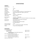
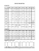
SPECIFICATIONS GENERAL Number of keys: 49 Polyphonic: 12-note Preset tones: 100 Transpose: F# ~ C ~ F: half-note Auto-rhythms: 25, Tempo: Adjustable, 216 steps (40 ~ 255), initial value: 120 Accompaniment: CASIO Chord, Fingered, Fill-in pattern, Synchro start Song bank: 20-tune Digital volume control: 10 steps (0 ~ 9), initial value: 7 Tuning control: 440 Hz ± 50 cents Built-in speakers: 10 cm dia.
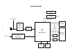
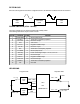
BLOCK DIAGRAM 7 seg. LED LED Latch IC2, IC3 MD0 ~ MD7 Phone/Output KO8 ~ KO11 —2— Amp.
CIRCUIT DESCRIPTION KEY MATRIX KI0 KI1 KI2 KI3 KI4 KI5 KI6 KI7 KO0 C2 G#2 E3 C4 G#4 E5 C6 KO1 C#2 A2 F3 C#4 A4 F5 KO2 D2 A#2 F#3 D4 A#4 F#5 KO3 D#2 B2 G3 D#4 B4 G5 KO4 E2 C3 G#3 E4 C5 G#5 KO5 F2 C#3 A3 F4 C#5 A5 KO6 F#2 D3 A#3 F#4 D5 A#5 KO7 G2 D#3 B3 G4 D#5 B5 KO8 0 1 2 3 4 Start/ Stop Up Volume Down KO9 5 6 7 8 9 Down Volume Down Synchro/ Fill-In K10 Tone Rhythm Song Bank Part Select One Key One Key K11 Step-1 Step
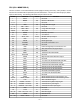
CPU (LSI1: MSM6755B-13) The CPU contains a sound data ROM and a DAC (Digital to Analog Convertor), and it provides a sound waveform in accordance with the pressed key and the selected tone. The CPU also controls key input, button input and LED driving. The following table shows the pin functions of LSI1. Pin No. 1 2 3~5 Terminal MA14 MWEB — In/Out — Out — Function Not used. Clock for LED latches Not used.
FILTER BLOCK Since the sound signal from the CPU is a stepped waveform, the filter block is added to smooth the waveform. Amp. IC301 Filter Block Q305 CPU LSI1 POWER AMPLIFIER (IC301: LA4598) The power amplifier is a two-channel amplifier with standby switch. The following table shows the pin function of IC301. Pin No. 1 Terminal Power GND In/Out In Function 2 3 4 Ch1 B.S. Ch1 OUT VCC — Out In Terminal for a bootstrap capacitor Channel 1 output +9V source 5 6 7 8 Ch1 N.F. Ch1 IN D.C.
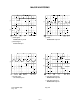
MAJOR WAVEFORMS 1 3 2 1 APO signal MSM6755B-13 pin 39 3 Clock MSM6755B-13 pin 32 2 Reset signal RH5VL40AA pin 1 5 4 6 4 Sound signal JH connector pin 2 5 LED drive signal LX0 MSM6755B-13 pin 88 6 LED drive signal LY1 MSM6755B-13 pin 81 Tone: Whistle (59) Key : A4 Key: D4 —6—
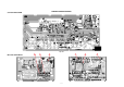
Main PCB JCM446-MA1M 6 5 3 Bottom view —7— 2 AVDD R320 R318 R302 1 Top view C328 JA3 C301 JA5 JA4 VC LED301 DVDD JA2 100 C352 75 L303 R333 R331 5 5 5 L304 L301 5 JA1 L302 L305 J302 D304 R303 R301 E VCC Q301 5 5 5 R317 B R316 125 150 100 5 R335 C355 150 R372 C330 R371 Q303 E R321 75 D334 R374 Q302 B R319 5 B 225 200 R370 R373 R C336 E R324 5 C331 R322 R369 C372 D302 B D335 C333 LVDD C332 Q310 E E 175 R368 C374 C342 100 C350 C373 R323 B Q304
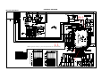
SCHEMATIC DIAGRAMS Main PCB JCM446-MA1M 2 5 4 Note: KI signals are renamed. (e.g.
Sub PCBs KDM445-MA2M/MA3M —9—
Keyboard PCBs KDM4910K-KY1M/KY2M — 10 —
LED PCB KDM446-LD1M — 11 —
LED PCB KDM445-LD2M PCB NAME — 12 —
LED PCB KDM446-LD3M PCB NAME LED PCB KDM445-LD4M PCB NAME — 13 —
EXPLODED VIEW 16 15 6 5 9 17 7 8 R-1 R-2 12 11 19 13 14 18 10 1 2 3 4 R-3 R-4 — 14 —
PARTS LIST CTK-220L Notes: This parts list does not include the cosmetic parts, which parts are marked with item No. "R-X" in the exploded view. Contact our spare parts department if you need these parts for refurbish. 1. Prices and specifications are subject to change without prior notice. 2. As for spare parts order and supply, refer to the "GUIDEBOOK for Spare parts Supply", published seperately. 3. The numbers in item column correspond to the same numbers in drawing.
Item Code No. Parts Name Main PCB 6925 6160 Main PCB ass'y (MA1M) 2012 4690 LSI, CPU 2105 5922 IC 2105 4452 IC 2105 5796 IC 2259 2555 Transistor, Chip, Digital 2259 2562 Transistor, Chip, Digital 2259 2646 Transistor, Chip, Digital 2259 2548 Transistor, Chip, Digital 2252 1239 Transistor, Chip 2390 2576 Diode, Chip, Schottky 2390 1820 Diode, Chip 2590 1526 Oscillator, Ceramic 2370 1141 LED, 7-seg.
Nov, 1996 MA1100761A