
User's Manual


Getting Ready
E-12
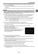
5. Perform the steps below to adjust the position and size of the Projector B image so
it slightly runs off the edges of the target screen, as shown in the “After adjustment”
image above.
z Take care simply to loosen the five screws. Do not remove them.
z After adjusting the position, re-tighten the fixing screws. Note that you will need to make fine
adjustments later in this procedure, so do not fully tighten the fixing screws at this point.
6. With both the Projector A and Projector B images being projected, repeat steps 3
and 5 as required to minimize the difference between the shape of the Projector A
and Projector B images.
Adjustment 2: Fine adjustment using the adjustment pattern
7. On the Control Box remote controller, press the [CORRECT] key.
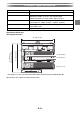
(1) Adjust the zoom ring of Projector B.
(2) Loosen the five screws that secure the cabinet side panels, and then rotate the adjuster knob to
adjust the orientation.
3
Before adjustment After adjustment
Fixing screws Adjuster knob Fixing screws