CTK-4000/CTK-5000/LK-270/LK-205/WK-200/WK-500/CDP-200R MIDI Implementation CASIO COMPUTER CO., LTD. Contents Part I 1 MIDI Message Overview Product Configuration as a MIDI Device.......................................................................................... 5 1.1 1.2 1.3 System Section.................................................................................................................................... 5 Performance Controller Section .............................................
9.13 9.14 9.15 RPN (64H,65H) ................................................................................................................................. 13 9.13.1 Pitch Bend Sensitivity .......................................................................................................................... 14 9.13.2 Fine Tune..............................................................................................................................................14 9.13.3 Coarse Tune.............
19.3 Format of Each Field ......................................................................................................................... 25 19.3.1 SX : System Exclusive Message Status ............................................................................................... 25 19.3.2 MAN : Manufacturer's ID .................................................................................................................... 25 19.3.3 MOD : Model ID.............................................
31 All Data Parameter ........................................................................................................................ 42 Part VI Parameter Set List 32 Parameter Set Table...................................................................................................................... 43 Part VII Setting Values and Send/Receive Values 33 Setting Value Tables......................................................................................................................
Part I MIDI Message Overview 1 Product Configuration as a MIDI Device In terms of a MIDI device, this Instrument consists of a System Section, Performance Controller Section, and Sound Generator Section. Each of these sections can send and receive specific MIDI Messages in accordance with its function. 1.1 System Section The System Section manages the Instrument status and user data.
1.3.2 Instrument Part Block The instrument parts of the sound generator can be operated or their settings can be changed with Instrument-specific system exclusive messages and channel messages. The 32 instrument parts of this Instrument are divided between Group A and Group B, each of which has 16 instrument parts. Only Group B can be controlled by external channel messages. As shown in the following table, there is a fixed relationship between channel message receive channel numbers and instrument parts.
2 Timbre Type Specific Operation The sound source operation performed for a received message depends on the current Timbre Type value (see "11.1 About the Timbre Type), which is the operation mode of each sound generator instrument part. For details, see the explanation for each message. 3 Conditions that Disable Message Send and Receive All MIDI message send and receive is temporarily disabled while any one of the following processes is in progress.
Part II Channel Message 4 Receive Channel The channel number of the channel message received by each part is shown in the table under "1.3.2 Instrument Part Block". 5 Send Channel Basically, the MIDI channel of the channel message sent when the Instrument is played coincides with the MIDI channel of the part being played. Note, however, that the MIDI channel of the performance information that corresponds to the keyboard main part is the Keyboard Channel setting value.
8 Polyphonic Key Pressure Format Message Format: AnH kkH vvH n: MIDI Channel Number kk: Key Number vv: Pressure Value Send This message is not sent by this Instrument. Receive This message is not received by this Instrument. 9 Control Change Format Message Format: BnH ccH vvH n: MIDI Channel Number cc: Control Number vv: Value Send Sent when the Instrument's pedal is operated or when Instrument settings are changed.
9.2 Modulation (01H) Format Message Format: BnH 01H vvH n: MIDI Channel Number vv: Value Send This message is not sent by this Instrument. Receive Receipt adds, to the tone being sounded, modulation of a depth specified by the value. In the case of a tone that already has modulation applied, receipt of this message increases the modulation depth. The modulation effect differs according to the tone being used. 9.
9.5 Pan (0AH) Format Message Format: BnH 0AH vvH n: MIDI Channel Number vv: Value (Note1) Note 1: For information about the relationship between setting values and send/receive values, see "33.3 Pan Setting Value Table" in "Part VII Setting Values and Send/Receive Values". Send Sent when auto accompaniment is used. Receive Receipt changes the pan setting of the corresponding part. 9.
Timbre Type Specific Operation This operation differs in accordance with the Timbre Type (see "11.1 About the Timbre Type") setting. • Timbre Type: Melody Sustain off/on control is performed in accordance with the value of the received message. • Timbre Type: Drum The received message does not affect sound source operation. 9.
Send Sent when auto accompaniment is used. Receive Changes Reverb Send. 9.11 Chorus Send (5DH) Format Message Format: BnH 5DH vvH n: MIDI Channel Number vv: Value (Note1) Note 1: The setting value matches the value that is sent and received. Send Sent when auto accompaniment is used and when a Chorus on/off operation is performed. Receive Changes Chorus Send. 9.
9.13.1 Pitch Bend Sensitivity Format Message Format: BnH BnH BnH BnH 64H 65H 06H 26H 00H 00H mmH llH n: MIDI Channel Number mm: MSB Value 0 - 12 ll: LSB Value Send 00H Receive Ignored Send Sent when the Bend Range is changed on the CTK-5000, WK-500, or CDP-200R. Receive Receipt changes Bend Range. 9.13.2 Fine Tune Format Message Format: BnH BnH BnH BnH 64H 65H 06H 26H 01H 00H mmH llH n: MIDI Channel Number mm: MSB Value ll: LSB Value Send This message is not sent by this Instrument.
Send This message is not sent by this Instrument. Receive Receipt changes Channel Coarse Tune. Does not affect sound source operation when the Timbre Type is Drum. 9.13.4 Null Format Message Format: BnH 64H 7FH BnH 65H 7FH n: MIDI Channel Number Send Sent after the Bend Range is changed on the CTK-5000, WK-500, or CDP-200R. Receive Receipt deselects RPN. 9.14 All Sound Off (78H) Format Message Format: BnH 78H 00H n: MIDI Channel Number Send Sent when Local is set to OFF on the Instrument.
10 Mode Message 10.1 All Notes Off (7BH) Format Message Format: BnH 7BH 00H n: MIDI Channel Number Send Sent when MIDI send related settings are changed on the Instrument, or when auto play is stopped, etc. Receive Receipt of any of this message releases the currently sounding voice (same as releasing the keyboard key). 10.2 Omni Off (7CH) Format Message Format: BnH 7CH 00H n: MIDI Channel Number Send This message is never sent.
10.5 Poly (7FH) Format Message Format: BnH 7FH 00H n: MIDI Channel Number Send This message is never sent. Receive Receipt of this message performs the same operation as when All Notes Off is received. 11 Program Change Format Message Format: CnH ppH n: MIDI Channel Number pp: Program Number (Note1) Note 1: For details about the relationship between the program number and the tone, see the Tone List that comes with the Instrument. Send Sent when a tone is selected.
12 Channel Aftertouch Format Message Format: DnH vvH n: MIDI Channel Number vv: Value Send These messages are never sent. Receive Receipt of this message adds modulation to the voice that is sounding. The modulation effect differs according to the tone being used. 13 Pitch Bend Format Message Format: EnH llH mmH n: MIDI Channel Number ll: Value LSB mm: Value MSB Send Sent when a pitch bender operation is performed on the CTK-5000, WK-500, or CDP-200R.
Part III System Messages 14 Timing Clock Format Message Format: F8H Send Sent when auto accompaniment is used. Receive This message is not received by this Instrument. 15 Start Format Message Format: FAH Send Sent when auto accompaniment is used. Receive This message is not received by this Instrument. 16 Stop Format Message Format: FCH Send Sent when auto accompaniment is used. Receive This message is not received by this Instrument.
Receive Once this message is received, the Active Sensing mode is entered. If no MIDI message is received for a specified amount of time, voices being sounded by the Instrument's sound source are released, the controller is reset, and the Active Sensing mode is exited. 18 System Exclusive Message Format Message Format: F0H....F7H The Instrument sends and receives standard universal system exclusive messages, and system exclusive messages that have Instrument-specific formats. 18.
18.1.3 Master Coarse Tuning Format Message Format: F0H 7FH 7FH 04H 04H 00H mmH F7H ll: LSB Value mm: MSB Value Send Sent when Transpose is changed. Receive Receipt changes the Transpose parameter. Does not affect sound source operation when the Timbre Type is Drum. 18.1.
Note 1: For information about the relationship between setting values and send/receive values, see "33.6 Chorus Type Setting Value Table" in "Part VII Setting Values and Send/Receive Values". Send This message is sent when the System Chorus Type setting is changed. Receive Receipt changes the System Chorus Type parameter. Rate Format Message Format: F0H 7FH 7FH 04H 05H 01H 01H 01H 01H 02H 01H vvH F7H vv: Value (Note1) Note 1: The setting value matches the value that is sent and received.
18.1.7 GS Message Message Format: F0H 41H ddH 42H 12H 40H 00H 7FH 00H 41H F7H Note: dd (Device ID) is ignored. Send This message is never sent. Receive Receipt performs the same operation as when the GM System On message is received. 18.2 Instrument-Specific System Exclusive Message Format Message Format: F0H 44H 16H 01H....
Part IV Instrument-Specific System Exclusive Messages 19 Format This section explains the format of the Instrument-specific System Exclusive Messages. See "Part V Parameter List" and "Part VI Parameter Set List" for information about how parameter sets actually are transferred. 19.1 Message Classifications Basically, the operation that corresponds to Instrument-specific system exclusive messages is parameter data transfer.
19.2 Basic Message Structure Instrument-specific system exclusive message operation can be broadly divided between two methods: Individual Parameter Transfer (single parameter send/receive) and Bulk Parameter Set Transfer (batch parameter send/receive). Each method includes a number of different messages. The field in the SysEx message that specifies the message type is the action (act) field. The format of the "body" part of the message depends on the "act" value.
19.3.4 dev : MIDI Device ID 00H-7FH Format: 0dddddddB The contents of this field in a received message are compared with the Model's MIDI Device ID, and receipt of the incoming message is allowed only when the two IDs match. When a message containing 7FH is received, receipt of the message is always allowed, regardless of the Instrument's ID setting. Note, however, that the Instrument does not have a specific Device ID, so use only 7FH for send and receive. 19.3.
HBS: Handshake Bulk Parameter Set Send Indicates a parameter set image send message using handshake mode. The parameter set to be transferred is divided into multiple packets when it is greater than a prescribed size. The packets are transferred in accordance with handshake mode. ACK: Acknowledge Indicates a message used by the receiver during parameter set handshake mode transfer to convey to the sender that it is ready for send of the next packet.
19.3.6 cat : Category Format: 0cccccccB 0cccccccB = Category (7bit) The category indicates the categories of data handled by the System Exclusive Message. The ID number (ID) of the Category is indicated on the left, while the communication operation (Action) is indicated on the right.
19.3.9 blk : Block Number The block number is a supplementary number that specifies which block parameter is to be accessed. Format: 0iiiiiiiB (LSB) 0jjjjjjjB 0kkkkkkkB (MSB) Block Bit Field Division When the parameter block has a multi-dimensional array structure, bit 21 of the block number is divided into prescribed bit fields based on the rules explained below.
19.3.13 len : Data Length Format: 0lllllllB (LSB) 0mmmmmmmB (MSB) As shown below, the meaning of this field differs depending on whether an individual transfer or a bulk parameter set transfer is being performed. Individual Parameter Transfer Data length indicates the length of the array being transferred minus 1 when the parameter contains a character string or other similar array structure. Bulk Parameter Set Transfer Data length indicates the number of bytes of data included within a packet.
19.3.16 img : Parameter Set Image Format: 0dddddddB 0cccccccB 000000abB For a bulk data transfer operation, the parameter set data to be transferred is read sequentially in 16-bit units starting from the top address. Read values are divided into 3-byte segments as shown below, and then sent in sequence. The following is the conversion format, which is the same as the individual parameter 16-bit transfer detailed above.
20 Individual Parameter Operations There are two parameter unit operations: Individual Parameter Transfer and Individual Parameter Request. For one session, in response to an IPR (Individual Parameter Request) from an external device, this Instrument returns an IPS (Individual Parameter Send) or the session is concluded when the external device or this Instrument spontaneously sends an IPS. If this Instrument received an IPS, the value of the applicable parameter is changed.
21.1.2 Session and Subsession Subsession "One subsession" refers to transfer of one parameter set. A subsession transfers one parameter set or a parameter set that has been divided into multiple packets for transfer, with EOD (End of Data) at the end to terminate the send. Division of a parameter set into multiple packets is used when the size of the parameter set is greater than a prescribed size.
21.3 Handshake Mode Communication Flow A session starts with the receiving device sending a request using a HBR, or with the sending device sending HBS data. The sending device does not send the next packet until it receives an ACK from the receiving device. The maximum wait time of at least 2000 msec is reserved. Failure of a response to arrive within the wait time is treated as a timeout error, and data communication is terminated.
The packed with the same packet number is resent when a checksum mismatch or incompatible data format error is detected. Data Receiver HBR Data Sender → ← ACK ERR Acknowledge HBS Data Send 1 HBS Data Send 2 (Retry 1) Error → ← ACK Data Send → ← ERR Send Request (Optional) HBS → ← Operation Error HBS Data Send 3 (Retry 2) → Acknowledge : : ACK → ← Acknowledge EOD End of Data EOS End of Session : Other subsessions : ← Session terminates if ERR is detected a number of times.
RJC is sent to terminate the session in case ACK cannot be recognized. Data Receiver Data Sender HBR → Operation Send Request (Optional) ← HBS Data Send : (Fixed amount of time elapses) RJC ← Timeout error The session can be canceled for any reason by sending an RJC. RJC can be sent by the sending device or the receiving device. The bulk dump session is terminated immediately upon receipt of an RJC.
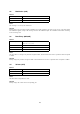
Data Receiver Data Sender Operation ← OBS Data Send BSY → Data Receiver Receive Rejected Data Sender Operation HBR → Send Request ← BSY Data Receiver Send Rejected Data Sender Operation ← HBS Data Send BSY → Receive Rejected 37
Part V Parameter List This section explains the parameters that actually can be transferred by the Instrument. 22 Using the Parameter List • Parameter field Shows the parameter name. • ID field Shows the parameter ID as a hexadecimal number. • R/W field Shows "R" to indicate that an IPR (Individual Parameter Request) read operation (Read) is possible or "W" to indicate that an IPS (Individual Parameter Send) write operation is possible.
23.2 Data Management Parameter These are information acquisition and operation command parameters for this Instrument's Data Manager PC application. Parameter ID R/W Block Size Array Min-Def-Max Description Ps Category 0005 W 000000 7 01 00-00-7F Specifies the category ID of the parameter set that corresponds to an operation. Ps Memory 0006 W ↑ 7 01 00-00-7F Specifies the memory ID of the parameter set that corresponds to an operation.
24 Patch Parameters The main function of patch parameters is to configure the settings of the sound source of a device. 24.1 Master Tune Parameter These parameters configure Master Tuning settings. Parameter Master Fine Tune Master Coarse Tune 24.2 ID R/W Block 0000 0001 R/W R/W 000000 ↑ Size Array 7 7 01 01 Min-Def-Max Description 00-40-7F 00-40-7F -100 - 0 - +99 (cent) -24 - 0 - +24 (semitone) Master Mixer Parameter These parameters configure the Master settings of the mixer.
25 Scale Memory Parameter Scale memory parameters store scale memory data. Parameter ID R/W Block Size Array Min-Def-Max Note 0000 R/W 000000 8 0C 00-80-FF A Key Mode 0001 R/W ↑ 1 01 00-00-01 26 Description -128 - 0 - +127 Array : Note 0....C 1....C# 2....D 3....D# 4....E 5....F 6....F# 7....G 8....G# 9....A 10...A# 11...B 0....Relative 1....Absolute Song Parameter The song parameter stores song data directory information.
30 Registration Parameter The registration parameter stores registration data directory information. Parameter Size 31 ID R/W Block 0001 R 000000 Size Array 32 01 All Data Parameter There is no parameter for storing all data directory information.
Part VI Parameter Set List This section explains actually how parameter sets can be transferred by the Instrument with bulk dump.
Part VII 33.4 Setting Values and Send/ Receive Values 33 Setting Value Tables 33.1 Off/On Setting Value Table -100 - 0 - +99 Setting Value Table Transmit/Receive Value Parameter (MSB-LSB) 33.5 00H-00H -100 : : 40H-00H 0 : : 7FH-7FH 99 Reverb Time Setting Value Table Transmit Value Receive Value Parameter Transmit/Receive Value Parameter 00H 00H - 3FH Off 00H OFF 7FH 40H - 7FH On 0CH 1 18H 2 24H 3 33.
Part VIII 34.2 MIDI Implementation Notation When a MIDI implementation data value is expressed in binary, the letter "B" (for "binary") is affixed at the end of the value. The table below shows the binary equivalents for the decimal values 0 through 127, which are often used for settings. 34 34.1 Value Notation Hexadecimal Notation MIDI implementation sometimes requires that data be expressed in hexadecimal format. Hexadecimal values are indicated by the letter "H" after the value.
CASIO COMPUTER CO.,LTD.