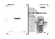
Data Collector Colector de Datos Datenerfassungsgerät Collecteur de Données M50RC/M70RC User’s Guide Guía del usuario Benutzerhandbuch Guide de l’utilisateur • Congratulations upon your selection of the CASIO DT-810M50RC/M70RC Data Collector. • Be sure to familiarize yourself with the basic operations described in this manual before actually trying to operate the Data Collector. • Enhorabuena por la selección del colector de datos DT-810M50RC/M70RC CASIO.
Safety Precautions Congratulations upon your selection of this CASIO Product. Be sure to read the following Safety Precautions before trying to use it for the first time. Keep this manual in a handy place for future reference. Markings and Symbols Danger! Warning! Caution! Marking examples The following are the meanings of the markings and symbols used in these Safety Precautions to warn you against the possibility of personal injury and/or material damage or loss to you and others.
Danger! ■ Lithium-ion Battery Pack ● Never allow the battery pack to become wet with either fresh water or salt water. Water can create the danger of battery pack heat emission, explosion, and fire. ● Never use or leave the battery pack next to open flame, near a stove, or any other area exposed to high heat. Doing so creates the danger of battery pack heat emission, explosion, and fire. ● Never use the battery pack with any device other than this unit.
Warning! ■ Disassembly and Modification ● Never try to disassemble or modify the unit in any way. High voltage inside creates the danger of electrical shock. ■ Interior Parts and Components ● Never touch interior high-voltage parts or components. Doing so creates the danger of electrical shock. ■ Abnormal Conditions ● Should the unit become hot or start to emit smoke or a strange odor, immediately turn off power and contact your original dealer or authorized CASIO service provider.
Warning! ■ Backup Battery Handling ● Do not throw the battery into fire, or heat, take apart or modify them. Doing so can damage the insulation or safety valves, and can create the danger of battery leakage, heat emission, and rupture. ● Do not use the battery with its positive (+) and negative (–) terminals reversed. Doing so can cause abnormal reactions by charging and shorting, and can create the danger of battery leakage, heat emission, and rupture.
Warning! ■ Lithium-ion Battery Pack ● Never place the battery pack into a microwave oven or any other highvoltage device. Doing so creates the danger of battery pack heat emission, explosion, and fire. ● Should the battery pack emit a strange odor or heat, change color or shape, or exhibit any other abnormal behavior, immediately stop using it. Continued use creates the danger of battery pack heat emission, explosion, and fire.
Warning! ■ Make back-up copies of all important data ● Note that CASIO Computer Co., Ltd. shall not be held liable to you or any third party for any damages or loss caused by deletion or corruption of data due to use of this, malfunction or repair of this unit or its peripherals, or due to batteries going dead.
Caution! ■ Backup Battery Handling ● Do not leave batteries in locations subject to strong direct sunlight or in high temperature locations such as in a car. Doing so can create the danger of battery leakage, heat emission, and rupture. ● Do not allow batteries to get wet with water. Doing so can create the danger of heat emission. ● Remove completely used batteries from the equipment immediately.
Caution! ■ Lithium-ion Battery Pack ● Never leave the battery pack in an area exposed to direct sunlight, in a car parked in direct sunlight, or any other very hot area. Doing so creates the danger of heat emission and fire, as well as deterioration of battery pack performance and shortening of its service life. ● Do not use the rechargeable battery pack in areas where static electricity is being generated. Doing so creates the danger of battery pack heat emission, explosion, and fire.
The following details are declared in the 15-country EU Union and 4-country EFTA Union. Product description/Intended use EU/EFTA member states intended for use Member states with restrictive use Manufacturer Brand Type EU: Austria, Belgium, Denmark, Finland, France, Germany, Greece, Ireland, Italy, Luxembourg, The Netherlands, Portugal, Spain, Sweden, United Kingdom EFTA: Switzerland, Iceland, Liechtenstein, Norway NONE CASIO COMPUTER CO., LTD.
The following Notified Bodies have been consulted in the Conformity Assessment procedure: Notified Body number 0122 Name and address NMi Certin B.V., PO Box 15, 9822 ZG Niekerk, The Netherlands The technical documentation as required by the Conformity Assessment procedure is kept at the following address: Company Address, City Country Phone number Fax number CASIO ELECTRONICS CO. LTD.
• The contents of this manual are subject to change without notice. • The term “Data Collector” as used in this User's Guide refers to the CASIO DT-810 Data Collector unless otherwise noted. • CASIO COMPUTER CO., LTD. assumes no responsibility for any loss or claims by third parties which may arise from the use of this manual. • This manual does not cover programming or the uploading of data. See the separate manual for details of these procedures. Contents Safety Precautions ..............................
Data Communication .......................................... E-30 DT-810 - DT-810 Data Communication ................................ E-30 Specifications ..................................................... E-31 DT-824LI Lithium-ion Battery Pack Specifications ............... E-32 Using the Optional Optical Communication Unit ....................................... E-33 General Guide .....................................................................
Unpacking When unpacking the Data Collector, check carefully to make sure that all of the items shown below are included. If anything is missing or damaged, contact your original dealer or your nearest CASIO Service Provider.
Introduction Make sure you carefully read the following information to ensure that your Data Collector is able to perform at the level for which it is designed. Handling Precautions • Never try to take the unit apart or modify it in any way. • Avoid leaving the Data Collector in direct sunlight, near heaters, or in any other area where it might be subjected to intense heat for long periods. Also avoid areas subjected to high humidity and large amounts of dust.
DT-810 System Diagram Options Optical Communication Unit High-speed Charger Unit Lithium-Ion Battery Pack DT-860IOE DT-820CHG DT-824LI Cables M50RC/M70RC DT-881RSC DT-882RSC DT-883RSC DT-888RSC DT-887AX AC Adaptor E-16 For High-Speed Charger Unit For Optical Communication Unit DT-9020ADP-G DT-9020ADP-U DT-825ADP-G DT-825ADP-U
General Guide • Front • Left side • Back • Right side 1 7 2 8 3 5 4 4 9 10 11 12 6 • Bottom 6 1 2 Reader port Read indicator 3 LCD screen and touch panel 4 Stroke keys 5 Reset button (inside cap) 6 7 8 Wrist strap hook Laser warning label Speaker 9 Back-up battery compartment 10 Main battery compartment 11 Main battery compartment lock 12 Charger/AC terminal 13 Infrared port 14 Touch panel stylus 14 13 13 12 Emits a laser for bar code reading.
Power Supply The Data Collector has both a main power supply (lithium-ion battery pack) and a backup power supply (lithium battery). In this manual, the words “main battery” refer to the lithium-ion battery pack. Low main battery power is indicated when the low voltage message appears on the LCD screen. Replace the main battery or charge the battery pack as soon as possible after the low voltage message appears. Important! E-18 • Never remove both the main battery and backup battery at the same time.
Installing the Lithium-ion Battery Pack 1 2 3 Slide the main battery compartment cover lock to the FREE position and remove the cover. Taking care to correctly orient the terminals of the battery pack, align the tab on the back of the supplied main battery compartment cover with the groove of the battery pack, and slide the battery pack onto the cover. Attach the main battery compartment cover to the Data Collector and slide the main battery compartment cover lock to the LOCK position.
Power Supply To remove the lithium-ion battery pack 1 2 Slide the main battery compartment cover lock to the FREE position and remove the cover. Slide the lithium-ion battery pack from the main battery compartment cover. Installing the Back-up Battery 1 2 E-20 Use a screwdriver to rotate the screw that secures the backup battery holder in place counterclockwise to loosen it.
3 4 Pull out the backup battery holder. Wipe off a CR2032 lithium battery with a dry cloth, and load it into the backup battery case so its plus (+) side is facing towards the holder (so you can’t see it). Insert from the hook side 5 Load the battery holder into the Data Collector and tighten the screw. To replace the Back-up Battery Replace the backup battery as soon as possible after the low voltage message appears on the display.
Power Supply 1 2 3 4 5 E-22 Use a screwdriver to rotate the screw that secures the backup battery holder in place counterclockwise to loosen it. Insert a screwdriver or some flat object into the back of the backup battery holder and pull out it. Pull out the backup battery holder. Remove the old backup battery. Wipe off a new CR2032 lithium battery with a dry cloth, and load it into the backup battery case so its plus (+) side is facing towards the holder (so you can’t see it).
Attaching the Wrist Strap The wrist strap protects the Data Collector against being damaged by dropping during transport. To attach the wrist strap 1 2 Pass the wrist strap through the metal wrist strap bar on the bottom of the data collector. Double the strap back through its own loop, and pull it tight. Important! • Never swing the Data Collector around by its wrist strap.
Keys and Their Functions Operations are controlled by 28 stroke keys and touch panel keys. Stroke Key Functions 1 2 3 1 1 2 3 6 4 4 5 7 8 E-24 5 6 7 8 Trigger key Triggers a bar code read operation. Any other function can also be assigned to this key. Control keys FNC key: Switches between the Function Mode and Normal Mode. BS key: Backspaces and deletes one character. LOCK key: Enables and disables user-defined keys. Multi-function (L/R) keys Keys that can be assigned any function.
Touch Panel Keys The touch panel on the LCD screen of the Data Collector can be operated with your finger or the supplied stylus to input data. Use of the stylus is recommended whenever you have problems operating the touch panel with your finger. Inputting alpha characters and punctuation Pressing the F1 (Alpha) key while the Data Collector is standing by for input enters the Alpha Mode and displays an alpha character touch panel screen.
Before Using the Data Collector for the First Time Be sure to perform the reset operation described below before using the Data Collector for the first time after you purchase it. Make sure Data Collector power is turned off. ↓ Use a paper clip or some other thin object to press the RESET button. ↓ Perform touch panel alignment. ↓ ↓ Perform a RAM drive check. If the drive is not formatted, display the check screen and format it. The system menu starts up.
4 Make the touch panel alignment. Using the stylus (pen) supplied with the unit, touch the centers of the 4 plus (+) marks in the order shown by the arrows. < CALIBRATION > Touch the center of mark by the pen which the arrow points. 5 Press on the menu to end the touch panel alignment. < CALIBRATION > Calibration Finished ! 1 : Retry 2 : End 6 Press to quit the SYSTEM MENU.
Using the Bar Code Reader Performing a Bar Code Read Operation 1 Turn on the Data Collector, position the reader port close to the bar code you want to read, and then press the trigger key. Reader port Read indicator Trigger key Power key 2 The reader port emits a laser to read the bar code. The read indicator lights green when the read is successful.
Scan Position When reading a small bar code, decrease the distance between the Data Collector and the bar code. For larger bar codes, position the Data Collector so that the bar code fits into the laser beam. Important! • Never look directly into the laser beam emitter or point the laser beam directly into someone’s eyes.
Data Communication DT-810 - DT-810 Data Communication Application software and input data can be transferred between two DT-810 units using the infrared ports on the bottom of the units. Position the two DT-810 units so they will not accidently move during data communication. The orientation of the two units depends on the type of communication you plan to perform. • Conformed IrDA Version 1.
Specifications • General CPU: Memory: 32-bit RISC Type M50RC: 2MB (RAM) M70RC: 10MB (2MB RAM + 8MB Flash ROM) • Display Type: Capacity: Display contrast: Backlight: STN LCD with phase correction film 160 x 160 dots Manually adjustable; includes automatic temperature compensation EL backlight • Laser Scanner Readable Codes: EAN, JAN, UPC, NW-7, CODE39, ITF, CODE93, CODE128, MSI, Industrial 2 of 5 Maximum Non-contact Distance: Approximately 38cm (Normal Mode), Approximately 25cm (High-resolution Mode) •
Specifications • Power Supply Main: Backup: One lithium-ion battery pack Battery life: Approximately four hours (using a fully charged new lithium-ion battery pack and repeating the following operations at normal temperature: reading a bar code for 1.5 seconds, sending radio data for 1 second, receiving radio data for 1 second and waiting reception for 6.
Using the Optional Optical Communication Unit The optional Optical Communication Unit (DT-860IOE) makes it possible to upload and download system data and file data between the Data Collector and a personal computer. It is also used to supply power for charging the lithium-ion battery pack. Be sure to use the specified RS-232C cable (DT-881RSC/DT-882RSC/DT-883RSC/DT887AX) to connect the Optical Communication Unit to a personal computer.
Using the Optional Optical Communication Unit 1 RS-232C connector 2 RS-422 connectors 3 4 AC adaptor jack For connection of an AC adaptor to supply power. Data Collector detection switch Detects whether or not the Data Collector is mounted correctly on the Optical Communication Unit. Charge/Power supply terminal Supplies power to the Data Collector mounted on the Optical Communication Unit. System operation indicator Indicates whether or not the system operation is normal.
Setting up the Optical Communication Unit and connect the Data Collector Use only the specified AC Adaptor for Optical Communication Unit to connect to an electrical outlet. Be sure to connect the AC adaptor and turn on Optical Communication Unit power before performing any data communication operation with the Data Collector. Power is supplied to the Data Collector by the Optical Communication Unit. 1 2 3 4 5 Plug the AC adaptor into an electrical outlet.
Using the Optional Optical Communication Unit Charging the Battery Pack The following procedure can be used only when a lithium-ion battery pack is loaded in the Data Collector. 1 2 Turn on the power of the Optical Communication Unit, and confirm that its power indicator lights up red. Attach the Data Collector to the Optical Communication Unit, making sure their infrared ports come into close contact with each other.
Setting the Optical Communication Unit You can hang the Optical Communication Unit on a wall or use it as a desktop unit. To use the Optical Communication Unit on a desktop Simply place the Optical Communication Unit on a desk, table, or any other flat, stable surface, rubber feet down. You can even use the wood screws to anchor the base onto a horizontal surface. If you do not anchor the base, make sure you locate the Optical Communication Unit where there is no danger of it falling.
Using the Optional Optical Communication Unit 3 Move the tab on the upper side of the Optical Communication Unit. ➀ Remove the two screws on the back that secure the tab. ➁ Press the tab down to the plate. ➂ Reattach the two screws removed in step ➀ to the holes on the upper side. Tab ➀ ➁ ➂ 4 5 6 E-38 Pressing in at the four corners of the Optical Communication Unit base, unhook the tabs and remove the base from the unit.
7 8 Reattach the base to the Optical Communication Unit, orienting it upside-down from what it was when you removed it, and secure it in place with the two screws. Hook the Optical Communication Unit onto the screws in the wall, and let it slide down to lock in place. Important! • Be sure to check the wood screws periodically for looseness and tighten when necessary after hanging the Optical Communication Unit on a wall.
Using the Optional Optical Communication Unit DIP Switch Settings The settings of the DIP switches located on the bottom of the Optical Communication Unit can be adjusted to achieve the desired hardware configuration.
DT-860IOE Optical Communication Unit Specifications Infrared Interface: Standard: Synchronization: Speed: Infrared Conformed IrDA Ver. 1.0 Original Asynchronous 9,600/38,400/115,200/230,400bps RS-232C Synchronization: Speed: Control Protocol: Asynchronous 2,400 to 115,200bps Full-duplex RS-422 Synchronization: Speed: Asynchronous 9,600/38,400/115,200/230,400bps Charger Charger Type: Charge Time: Fixed voltage (with current limiter) Approximately 2.
Using the High-Speed Charger Unit The optional DT-820CHG High-Speed Charger Unit provides high-speed charging of a lithium-ion battery pack (which is not loaded in the Data Collector). General Guide 3 2 1 1 Charge indicator Indicates the charge status of the lithium-ion battery pack. Off: Not charging Red: Charging Flashing Red: Defective battery pack Green: Charging complete Flashing Green: Temperature outside of allowable charging range (Charging will resume with a return to normal temperature).
3 Insert the lithium-ion battery pack you want to charge into the High-Speed Charger Unit with its terminals facing down. This causes the CHARGE indicator to light red to indicate that charging has started. The following shows how the charge indicator shows the status of the charge. Lit Red: Charging Lit Green: Charge complete Flashing Red: Battery pack problem Flashing green: Charging interrupted because ambient temperature is outside of allowable range for charging.
Using the High-Speed Charger Unit DT-820CHG High-Speed Charger Unit Specifications Charger Charger Type: Charge Time: Fixed voltage (with current limiter) Approximately 2.
Safety Precautions Congratulations upon your selection of this CASIO Product. Be sure to read the following Safety Precautions before trying to use it for the first time. Keep this manual in a handy place for future reference. Markings and Symbols Danger! Warning! Caution! Marking examples The following are the meanings of the markings and symbols used in these Safety Precautions to warn you against the possibility of personal injury and/or material damage or loss to you and others.
Data Collector Colector de Datos Datenerfassungsgerät Collecteur de Données M50RC/M70RC User’s Guide Guía del usuario Benutzerhandbuch Guide de l’utilisateur • Congratulations upon your selection of the CASIO DT-810M50RC/M70RC Data Collector. • Be sure to familiarize yourself with the basic operations described in this manual before actually trying to operate the Data Collector. • Enhorabuena por la selección del colector de datos DT-810M50RC/M70RC CASIO.