
User manual - DT-810M50RC


E-34
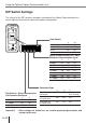
Using the Optional Optical Communication Unit
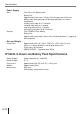
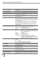
1 RS-232C connector For connection of a PC and uploading/downloading of system data
and file data.
2 RS-422 connectors For connection of multiple optional Optical Communication Units.
3 AC adaptor jack For connection of an AC adaptor to supply power.
4 Data Collector detection switch Detects whether or not the Data Collector is mounted correctly on
the Optical Communication Unit.
5 Charge/Power supply terminal Supplies power to the Data Collector mounted on the Optical
Communication Unit.
6 System operation indicator Indicates whether or not the system operation is normal. A system
operation problem is indicated when this indicator does not light up
green shortly after the Data Collector is mounted onto the Optical
Communication Unit.
Off: All Data Collectors mounted on the Optical Communication
Units are unable to communicate, or there is a system problem.
Lit Green: Normal system operation. One or more of the Data
Collectors mounted on the Optical Communication Units are
communicating.
7 Data communication indicator Indicates the status of data communication operations.
Off: Not communicating
Flashing Green: Communication in progress
Lit Red: Optical Communication Unit connection problem
8 Charge indicator Indicates the charge status of the lithium-ion battery pack.
Off: Not charging (Data Collector battery compartment
contains alkaline batteries)
Lit Red: Charging
Lit Green: Charging complete
Flashing Red: Battery pack problem
Flashing Green: Charging interrupted because ambient
temperature is outside of allowable range for
charging. Charging will resume when temperature
is back within the allowable range.
9 Power indicator Indicate whether power is on or off, and if the Data Collector is
mounted.
Off: Power off
Red: Power on, Data Collector not mounted
Green: Power on, Data Collector mounted
10 Infrared port This port provides contact-less infrared communication capabilities
with a Data Collector.
11 Power switch Turns power on and off.
12 Base Reverse the position of the base when wall mounting the Optical
Communication Unit.
13 DIP switches Use these switches to set the operational configuration of the
Optical Communication Unit.
14 Wall mounting tab Secures the Data Collector when mounting it on a wall.
15 Wall mounting hole Use this hole to attach the Optical Communication Unit to a hook
on a wall.