DT-X11 Series Software Manual (Version 1.01) CASIO Computer Co., Ltd. Copyright ©2006. All rights reserved.
Table of Contents Chapter Chapter 1 1.1 1.2 2 2.1 2.2 2.2.1 2.2.2 2.2.3 2.3 3 3.1 3.1.1 3.1.2 3.1.3 3.1.4 3.1.5 3.1.6 3.1.7 3.1.8 3.2 3.2.1 3.2.2 3.2.3 3.2.4 3.2.5 3.2.6 3.2.7 3.3 3.3.1 3.3.2 3.3.3 3.3.4 3.3.5 3.3.6 3.3.7 3.3.8 3.3.9 3.4 3.4.1 3.4.2 3.4.
Chapter 3.5 3.5.1 3.5.2 3.6 3.6.1 3.6.2 3.6.3 3.6.4 3.6.5 3.6.6 3.6.7 3.6.8 3.6.9 3.7 3.7.1 3.7.2 3.7.3 3.7.4 3.7.5 3.7.6 3.8 3.8.1 3.8.2 3.8.3 3.8.4 3.8.5 3.8.6 3.8.7 3.8.8 3.9 3.9.1 3.9.2 3.9.3 3.9.4 4 4.1 4.1.1 4.1.2 4.1.3 4.1.4 4.1.5 4.1.6 4.1.7 4.1.8 4.1.
.1.10 4.1.11 4.1.12 4.1.13 4.1.14 4.1.15 4.1.16 4.1.17 4.1.18 4.1.19 4.1.20 4.1.21 4.1.22 4.1.23 4.1.24 4.1.25 4.1.26 4.1.27 4.1.28 4.1.29 4.1.30 4.2 4.2.1 4.2.2 4.2.3 4.2.4 4.2.5 4.2.6 4.2.7 4.2.8 4.2.9 4.2.10 4.2.11 4.2.12 4.2.13 4.2.14 4.2.15 4.2.16 4.2.17 4.2.18 4.2.19 4.2.20 4.2.21 4.3 4.3.1 4.3.
Chapter 4.3.3 4.3.4 4.3.5 4.3.6 4.4 4.4.1 4.4.2 4.4.3 5 5.1 5.2 5.3 5.4 5.
Editorial Record Manual Version no. 0.90 1.00 1.01 Date edited February 2006 April 2006 September 2006 Page Content Tentative version Original version The content about the AC adaptor is added in Table 1.2 of Chapter 1.2. The “ “ notations in Table 3.23 of Chapter 3.2.4 are changed to “T” notations. The explanation about “T” notation is added in Table 3.24 to 3.36 of Chapter 3.2.4.
Preface This reference manual describes a product overview of the DT-X11 series handheld terminals.
1. Product Overview CASIO has extended its product line-up by adding this successor model of DT-X10 series that is high-performance handheld terminal compatible with various industrial communication standards and with a built-in CMOS Imager or Laser Scanner (model dependant) aiming at the following challenges. • Acquire new users and fulfill replacement demands from the transport industry.
1.1 Features Incorporates .NET technology • • • Uses WindowsCE 5.0 Operating System. Makes effective use of the .NET resources developed by other parties. Employment of Embedded OS makes it possible to build a flexible WindowsCE system. Enhanced communicating functions • • • • • Covers GPRS/WLAN, etc. by using various communication cards. Built in Bluetooth Ver 1.1 module. The target transfer rate of the WLAN is 5 Mbps, which is the maximum rate of communication for peer-to-peer connection with PC.
Aiming to a full compliance with the “Restriction of the use of certain Hazardous Substances in electronic equipment (RoHS)” set mandatory on July 1 2006 The following products have been assembled with devices, components and parts manufactured using Lead (Pb) free solder.
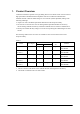
1.2 Available Options The following dedicated options are available for the DT-X11 series. Table 1.2 Option Cradle Battery Battery charger AC adaptor Product Bridge Satellite Cradle Battery pack (Standard) Large-capacity battery pack Dual battery charger Cradle-type battery charger Car Mounted Battery Charger AC adaptor Model no.
2. Applications This chapter describes some of the usage scenarios for the DT-X11 series handheld terminal. 2.1 System Configuration by Application 1. T Terminal for automobile drivers WWAN Card • Transmits data in real time input at a customer to the center • Receives/sends instruction e-mails to/from the center. Car Mounted Battery Charger IrDA or Bluetooth Portable printer Fig. 2.1 2. Terminal for warehouse application WLAN Card Transmits data in real time input in the office via WLAN.
3. Terminal in WAN and LAN configuration WLAN Card WWAN Card Transmits data in real time input in the field through WWAN, and in the office through WLAN. Charger IrDA or Bluetooth Portable printer Fig. 2.3 4. Terminal in conventional configuration • Temporarily stores input data in this terminal without using a communication card, then uploads it to connected PC. Cradle IrDA or Bluetooth Portable printer Fig. 2.
2.2 Operation by User Assuming actual operation is performed by the end user, this chapter describes the method of use and restrictions that apply to the terminal, including the optional devices. 2.2.1 • • • • • • Basic Operations For operating the touchpanel it is recommended to use the accompanied stylus, since direct operation with your fingers may cause a malfunction or soil the screen. The Trigger keys are designed and built so that the terminal can be held by single hand to scan symbols.
2.2.2 Operation with Multiple Options Since many built-in devices and externally connected optional devices may co-exist, the user must observe some precautions and restrictions when using them concurrently. Optional devices available for the DT-X11 A -PCMCIAWLAN card GPRS CARD B D -CF- (Expansion slot) FROM CARD WLAN CARD GPRS CARD Device recommended by CASIO -IrDA- Connecting Bridge Satellite Cradles Connecting HTs Printer D C -Bluetooth- Printer Cellular phone, etc.
Table 2.
2.2.3 Intended Application by Device Table 2.3 Device FROM card Modem card LAN card WLAN card Printer Cellular phone Battery charge on Cradle Connecting to Bridge Satellite Cradle Connecting HTs PCMCIA CF Bluetooth IrDA Yes Yes Yes - Yes Yes Yes - Yes Yes - Yes - Charge terminal Yes - - - Yes Yes - - Yes Yes - FROM Card Used as the storage memory.
LAN Card Used to perform communication by connecting to the 10BASE-T Ethernet environment. • Permanent LAN connection (operating the terminal as desktop unit) • Independent LAN connection (connecting the LAN cable or LAN card as required) • Real-time upload/download of information • Send and receive mail • Security function (VPN (PPTP)) • To secure data, access is stopped when the battery pack cover is opened.
Bridge Satellite Cradle It features with two types of serial interface, RS-232C and USB, for connection with a PC. This cradle supplies power to the terminal as well as charging the battery pack. By connecting cradle-to-cradle via RS-422 interface it is possible to chain-connect a maximum of 8 handheld terminals. Application 1 Data Data Data Database Between Bridge Satellite Cradle and HT : FIR (4Mbps) Connection via RS-232C / USB interfaces Fig. 2.
2.3 Application Development Environment Development platform • • Microsoft Windows 2000 (SP2 or later release) Microsoft Windows XP Development environment • • • Visual Studio 2005 Visual Studio .NET 2003+WindowsCE Utilities for Visual Studio .NET 2003 Add-on Pack 1 eMbedded Visual C++ 4.0 +SP4 T T Development environment • DT-X11 Export SDK Visual Studio .NET 2003 and Visual Studio 2005 • • • • • • • • VCC++ application development for the DT-X11 using Visual Studio 2005 is not supported.
3. Functions This chapter describes about detailed specifications of the functions implemented in the terminal and the options. 3.1 Basic Functions 3.1.1 WindowsCE Version 5.0 The terminal integrates Microsoft WindowsCE Version 5.0 as its operating system. Features at a glance • • • • • • • Easy-to-use user interface .
Core Modules Microsoft core modules integrated in the terminal are as follows. Table 3.1 Core OS Modules -.NET Compact Framework 1.0 .NET Compact Framework -- SQL Server CE 2.0 .NET Data Provider -- .NET Compact Framework 1.0 Related Matters Yes Smart Device Authentication Utility Yes .NET Compact Framework 2.0 Applications and Services Development SQL Server 2000 .NET Data Provider .NET Compact Framework 2.0 Yes SQL Server CE 2.0 .
OBEX Client Yes Object Exchange Applications and Services Development Protocol (OBEX) Message Queue (MSMQ) Yes OBEX Server OBEX File Browser Yes OBEX Receive Tray Yes Yes MSMQ ActiveX Wrapper Yes SOAP Reliable Message Protocol (SRMP) Yes Yes COM COM Storage Area CoCreateGuid Function for OLE32 Yes Yes Yes Component Service (COM and DCOM) Component Object DCOM Model COM Storage Area -DCOM Remote Access --- Minimum COM (OLE COM Storage Area unsupported) CoCreateGuid Function For OL
Yes Audio Playback Redirect -- Applications - End User Serial and Parallel Port Redirect Yes Smart Card Redirect --- Remote Desktop Remote Desktop Printer Redirect Connection Protocol (RDP) User Interface Dialog Box Yes Cut/Copy/Paste Clipboard Redirect Yes File Storage Area Redirect Yes Filtered File Storage Area Redirect Yes Word Pad Yes Receive Tray Yes PNP Notification Yes Yes USB Human Input Device (HID) USB Host Support Class Driver -USB HID Keyboard and Mouse -- USB HID K
Core OS Services Debug tool LMemDebug Memory Device Hook -- Keyboard Test Application -- Touch Driver Test Application -- Tool Hint API Yes Remote Display Application -- Small Kernel Test Sample Application -- Battery Driver Yes Parallel Port Support -- Notification (select UI Base Notification Yes one) Non-UI Base Notification -- Notification LED Support Yes Power Control (select Yes one) Power Control (full) Power Control (minimum) -- FTP Server Yes RAS Server/PPTP Server
Native Wi-Fi WLAN Access Point Component -- Network - Local Area Native Wi-Fi WLAN STA Yes Network (LAN) Wired Local Area Network (802.3, 802.5) Yes Wireless LAN (802.11) STA - Auto Configuration and 802.
IPSec v4 Yes NDIS Packet Capture DLL Yes NDIS User Mode I/O Driver Yes Yes TCP/IP IP Help API Yes TCP/IPv6 Support Yes Communication Services and Networking USB Flash Configuration Tool -- Windows Network API/Redirect (SMB/CIFS) Yes Winsock Support Yes Internet Yes Connection Share Gateway Log (ICS) -- Gateway User Interface Reference Network Functions -- Domain Search Yes Network Driver Configuration (NDIS) Yes Network Bridge Function Yes Network Utility (IpConfig, Ping, Ro
File Systems and Data Store System Password Yes Database Support Yes File system - Internal (select File System Applicable for RAM and ROM one) File System Only Applicable for ROM -- Duplication of File and Count Base -- Database (select one) Bit Base Yes Registry Storage Area (select Hive Base Registry Yes one) RAM Base Registry -- Compression Yes Yes Storage Area Manager Arial Comic Sans MS CD/UDFS File System -- EDB Database Engine Yes FAT File System Yes Transaction Safe
Tahoma (Subset 1_07) Tahoma Yes Tahoma Bold -- Times New Roman (Subset 1_30) Fonts Times New Roman Trebuchet MS Verdana Yes Times New Roman Bold -- Times New Roman Bold Italic -- Times New Roman Italic -- Trebuchet MS -- Trebuchet MS Bold -- Trebuchet MS Bold Italic -- Trebuchet MS Italic -- Verdana -- Verdana Bold -- Verdana Bold Italic -- Verdana Italic -- Webdings -- Wingding Yes Symbol Yes Unicode Script Processor Supporting Complex Scripts -English (American) Onl
Punjabi India Hindi Marathi International Thai Local Specific Support German Input System French Input System Keyboard Punjabi Keyboard -- Font Raavi -- Keyboard Hindi Traditional Keyboard -- Font Mangal -- Keyboard Marathi Keyboard -- Font Mangal -- Keyboard Thai Kedmanee Keyboard -- Font Tahoma (Subset 1_08) -- Transcriber Handwriting Recognition Application Transcriber Handwriting Recognition Application Keyboard Hebrew English (Global) English (American) Font Input S
Agfa AC3 Font Compression -- GB18030 Data Conversion -- SC_Song -SimSun and NSimSun SimSun and NSimSun (Subset 2_20) SimSun and NSimSun (Subset SimSun Font and NSimSun (select one) 2_50) SimSun and NSimSun (Subset 2_60) SimSun and NSimSun (Subset 2_70) SimSun and NSimSun (Subset 2_80) International SimSun and NSimSun (Subset Local Specific Simplified Support Chinese 2_90) Pocket IME ---Yes ----- Double Spell Software Keyboard - Small --- 1.1MB Minimum MSPY 3.
Agfa AC3 font compression -- Gulim (GL_CE) Gulim and GulimChe (Subset 1_30) Font Gulim and GulimChe (select one) Korean Gulim and GulimChe (Subset 1_40) Gulim and GulimChe (Subset 1_50) Gulim and GulimChe (Subset 1_60) Input System --Yes --- Korean Software Keyboard Sample -- Handwriting -- Recognition Engine MboxKOR HWX Sample UI -- (HWX) International Input System Editor Local Specific IME 97 -- Agfa AC3 Font Compression Support -MS Gothic, MS P Gothic and MS UI Gothic MS Gothic, MS
Kana Keyboard -- View of All Characters -- T Alphanumeric/English Software Keyboard -- T Stroke Count Search Input System Handwriting Recognition Engine (HWX) T T -- T T -- T Multibox HWX Sample UI T -- T Character Auto Complete - HWX T -- T Sample UI Radical Search T --- IME 3.1 Database Compact Database -- (select one) Standard Database -- System Tray Icon Japanese IME International 3.
Handwriting Recognition International Input Local Specific Traditional Support Chinese Engine (HWX) System -MboxCHT HWX Sample UI -- Phonogramic Input (Bopomofo) -- Radical Input (Chang Jei) -- Pocket IME -- Input System Editor Input System Manager (IMM) Yes Multilingual User Interface (MUI) -- Pocket Internet Explorer HTML View (WEBVIEW) Yes Yes Internet Explorer HTML Application Yes Internet Explorer Internet Explorer Theme Library Yes HTML/DHTML Internet Explorer Yes API Pl
Yes Internet Client Services JScript 5.6 Script Encode (Jscript) Script Authoring (Jscript) Script MagBox and InputBox Support Yes Script Encode (VBScript) Yes Script Authoring (VBScript) Yes Pocket Internet Explorer -Yes Internet Explorer 6.0 for WindowsCE - Internet Explorer 6.0 Sample Browser Yes Standard Component TV Style Navigation Component Yes Waveform Audio Audio Yes -- Audio Compression Manager GSM 6.
DirectShow ACM Wrapper Filter -- DirectShow Error Message -- DirectShow Core DVD - Video Yes DirectShow Display -- DMO Wrapper Filter -- DVD - Video -- DVD - Video Sample -- Windows Media Player -- Windows Media Player OCX --- Windows Media Multimedia Technologies Player ASX v1 and M3U File Support -- ASX v2 File Support -- ASX v3 File Support -- Windows HTTP Windows Media Streaming -- Media MMS Windows Media Streaming -- Technology NSC File Support -- Windows Media Mul
Multimedia Technologies Media DirectShow Video Renderer -- MPEG-1 Video Codec -- Video Codec and MS RLE Video Codec -- Renderer WMV/MPEG-4 Video Codec -- Overlay Mixer -- Media Format Video/Image Compression Manager -- AVI Filter -- MPEG-1 Passer/Splitter -- Microsoft Certificate Registration Tool Sample Yes Local Authentication Yes Subsystem Password Local Authentication Plug in Yes Yes Security Powerful Encrypting Provider’s Encrypting Service (CryptoAPI 1.
Quarter VGA Resource Longitudinal Mode Yes Overlap Menu -- Controls Option B Customizable UI -Sample Skin Resembling Windows XP screen -Shell and User Interface Control Panel Applet User interface -Yes Software Input Software Base Input Panel SIP for Small Screen Panel (SIP) (select one or more) SIP for Big Screen Yes -- Software Base Input Panel Driver Yes Touch Screen (stylus) Yes Network User Interface Yes Mouse -- Menu Hint Yes User Aid -Animation Control Shared Control Sha
3.1.2 Displays Basic Specifications The QVGA (320 x 240 dots) mode is supported for the terminal. Table 3.2 Display specification X direction Display size Y direction 65,536 colors 2-way TFT (16 bpp, Red: 5 bits, Green: 6 bits, Blue: 5 bits) 240 dots 320 dots Contrast • Can be set in the range of 1 to 9 (Default = 5). • Can be set in application with ExtEscape()API function. • Setup values can be modified in the Brightness properties.
Auto Backlight OFF (in both cases powered by battery pack and via Cradle/Battery charger) The Control Panel can be used to set up whether or not the auto backlight off function is used and the waiting time until when the auto backlight off function activates. The auto backlight off function is effect for both when the power is provided by an external power source and when it is provided by lithium-ion battery pack.
3.1.3 Keys Keyboard Layout The following is the keyboard layout employed in the DT-X11. Fig. 3.
Key Assignments The following are the key codes and functions assignments. Table 3.3 Control keys KEY Input mode Operation Remarks Fn mode is released Fn/□ ---- Specialized key operation (toggle) when a key input is made. Programm able (○) CLR Returns the VK code set in the registry (Default: VK_F25). ProgKeyCode : DWORD Character input mode Function mode ENT [HKEY_LOCAL_MACHINE\HARDWARE\DEVICEMAP\KEYBD] ---- Character input mode Function mode 1 Deletes 1 character..
Table 3.4 Function key KEY Input mode Character input mode F1/BS Operation Remarks Deletes 1 character to left. Initiate application registered in the registry below. Function mode [HKEY_LOCAL_MACHINE\Software\Microsoft\Shell\Keys\40C1] Character input mode Perform as “Hyphen”. Default:sz (path of the application to be initiated) F2/- Initiate application registered in the registry below.
Table 3.6 KEY 0 Ten key Input mode Character input mode Character input mode Function mode 2 3 5 Perform as “‘<,>?/{[]}”. F Display or not display SIP. 1 Perform as “1”. A No effect. a No effect. Turn on or off the backlight. Perform as “2”. Character input mode A Perform as “ABC”. a Perform as “abc”. Function mode F Decreases the contrast. 1 Perform as “3”. Character input mode Character input mode A Perform as “DEF”. a Perform as “def”. F Increases the contrast.
KEY Input mode Operation 1 Character input mode 8 Remarks Perform as “8”. A Perform as “TUV”. a Perform as “tuv”. Initiate application registered in the registry below. Function mode F [HKEY_LOCAL_MACHINE\HARDWARE\DEVICEMAP\KEYBD] Fn8LaunchPath:sz (path of the application to be initiated) 1 Character input mode 9 Perform as “9”. A Perform as “WXYZ”. a Perform as “wxyz”.
Key Input Mode Switchover The F4/Alpha Key on the keyboard can be used to change the key input mode. Indication of Key Input Mode Key input mode currently specified appears in the task tray. The modes that can be displayed are “L” as Lock, “F” as function, “1” as numeral, “A” as alphabets in uppercase, and “a” as alphabets in lowercase. L F 1 A a Fig. 3.
Enabling/Disabling Fn Key For keys that perform specialized operations while the key input mode has been set to Function mode, “Enable” or “Disable” can be set on each individual key in the registry below to control the operations. [HKEY_LOCAL_MACHINE\HARDWARE\DEVICEMAP\KEYBD] Table 3.
User Settable Keys • Initiating application The following registry can be used to assign any application to the Fn+7, Fn+8 and Fn+9 keys. [HKEY_LOCAL_MACHINE\HARDWARE\DEVICEMAP\KEYBD] Table 3.8 Key Fn7LaunchPath Fn8LaunchPath CardLaunchPath Setting Value sz: Target application in full path to initiate sz: Target application in full path to initiate sz: Target application in full path to initiate The following registry can be used to assign any application to the F1, F2, F3 and F4 keys.
3.1.4 Touch Panel An input can be made into any portion of the screen on the touch panel. The touch panel has the following resolutions. Table 3.11 Resolution • • X direction Y direction 240 dots 320 dots Capturing touch coordinates, X and Y directions, and controlling the pointing are possible by application. Prior to using the touch panel for the first time, calibrating the touch panel is required. Tap Sound The Control Panel can be used to set up the tap sound to mute, low or loud.
3.1.5 Audio Basic Specifications WAV playback, and voice recording are supported. Stereo data is converted into mono data and then output. By using the Microsoft SoftwareMixer function, output sounds from multiple applications can be mixed and output (in 44.1 KHz, 16-bit stereo mixing). The terminal supports WAV standards. Playback Table 3.12 Sampling frequencies Stereo/Mono KHz 8 11.025 12 16 22.
3.1.6 Buzzer Basic Specifications The buzzer can be used to output various sounds such as scanning confirmation, key click, tapping, alarm, warning and any other available sounds. The buzzer sounds are not output to the headphones. To output them to the headphones, instead of the buzzer sound, use PlaySound() API function which uses the audio driver. The sounds have the following six attributes and default values. Table 3.
3.1.7 Memory Management RAM The integrated RAM has a total capacity of 64 Mbytes and is used for the following purposes. • Program memory to be used by the OS and programs. • Object store used for temporary file saving, etc. • Other program and OS resident areas beyond the control by the OS • Buffers for display and camera • Driver work area The user can make unrestricted use with the object store, but data stored in it may be lost due to battery exhaustion, etc.
FlashDisk The Flash Disk has 128MB as its total capacity. The disk is released as user disk and can be accessed as FlashDisk folder. The user disk is available to freely read/write user data such as user application, master data, transaction data, etc. The Flash Disk different from RAM does not require a power to back up data in the disk, so data is not lost even if the terminal’s memory backup battery is exhausted. Be sure to back up important data files in the RAM to the Flash Disk.
3.1.8 LED Basic Specifications There are two LEDs integrated in the terminal, one for the user notification on the right and the other for charging the battery complete on the left. Table 3.
User Definition This indication mode is used for other notifications freely defined by the user. The ON/OFF state can be controlled by use of the Common Device Control Library. Table 3.19 Specifications Operation mode User definition Specification Color selection from green, blue, or orange. Programmable for ON and OFF time periods Note: Indication for scanning a bar code has the priority over other indications.
3.2 Laser Scanner (DT-X11M10E/M10RC) 3.2.1 Basic Specifications The following industrial standard bar code symbologies are supported by the laser scanner integrated in the terminal (model dependant). Table 3.
6. Minimum and maximum digits on IATA symbology The minimum no. of digits can be set to 15 or 17 for the maximum only when the IATA check digit calculation is set to “Coupon number and Calculate data segment” or “Calculate just data segment”. 7. Maximum digit on RSS Expanded symbology The maximum digit count for just numeric data is 74. The maximum digit count for just alphabet data is 41. • • The maximum no. of digits for each symbology in Table 3.
3.2.2 Scanning Method The laser scanner has “scanning state” (emits laser beam to read a bar code) and “standby state” (scanning is halted and in standby state). These two states are controlled to start scanning bar code and stop the scanning. Table 3.21 Scanning methods Scan method Single scan Continuous scan (controlled with trigger key) Continuous scanning (controlled by program) Description Conditions for scanning to end Press the trigger key to start scanning.
3.2.3 Scanning Parameters Conditions that allow scanning a symbology in specific modes can be set for each readable symbology. Readable Symbology Bar code symbologies that are enabled or disabled for scanning can be specified. If only specific symbologies are to be scanned, set “Enable” for scanning on these symbologies only and “Disable” on the other symbologies. This will reduce decode processing time and lower the error rate. The default is “Enable scanning on all the symbologies”.
No. of Scanning Times In “Continuous Scanning” mode, scanning continues for the preset number of scanning times and then it will stop in waiting mode. The number of times for scanning can be set in the range of 1 to 9 either at the Control Panel or using the Common Device Control Library. The default is 1. Scanning Period Valid time period of scanning after the trigger key is pressed down can be set in the range of 1 to 9 either at the Control Panel or using the Common Device Control Library.
3.2.4 Scanning Output Format Formats for outputting results of scanned bar codes can be set. Table 3.
Symbology Standard UPC-E UPC-E UPC-E (see note) No.
Code93 Code128 Code128 AAA ------- AAAT 1 to Max AAA ------- AAAT 1 to Max SBBB ------- BBCST See Table 3.30 "Code128 symbology” 1 to Max AAA ------- AAAT for meanings of the notations. 1 to Max SBBB ------- BBCST 1 to Max FAAA ------- AAAT 1to Max GAAA ------- AAAT MSI 1 to Max DDD ------- DDCCT IATA 1 to Max EAN-128 See Table 3.29 "Code39 symbology” 1 to Max RSS-14 RSS Limited RSS Expanded for meanings of the notations. See Table 3.
Table 3.27 D C T Data Check digit (mod 10) Becomes data if there is no check digit Termination code Table 3.28 D C T Interleaved 2of5 symbology Industrial 2of5 symbology Data Check digit (mod 10) Becomes data if there is no check digit Termination code Table 3.29 Code39 symbology A B ASCII conversion post data ASCII conversion pre data C Check digit (mod 47) Becomes data if there is no check digit S T Start/Stop character Termination code Table 3.
Table 3.34 RSS-14 symbology D C T Numeric data Check digit (mod 10) Termination code Table 3.35 RSS Limited symbology D C T Numeric data Check digit (mod 10) Termination code Table 3.
Termination Codes Select one of the following five termination codes to attach to the end of decoded data. - CR - LF - CR+LF - TAB - No termination code The default is “No termination code”. Output Buffer The scanner scans a bar code and outputs the scanned data using one of the following methods described in the table below. Table 3.37 Output Method OBR buffer output (see note) Key message output Clipboard output Keyboard output - Description Scanned data is output to memory in the laser scanner driver.
Scan Completion Notification When scanning is completed, a notification is issued to the application using one of the methods described in the table below. Each notification method can be set to “Enable” or “Disable”. The default is “Notification with window message”. Table 3.38 Method Window message Event None Description A window message is issued to the specified window handle. Also, the conditions for scanning completion can be fetched by referring to wParam parameter of the window message.
3.2.5 Scan Result Notification When scanning a bar code is completed, a notification about the scanning result can be indicated to the user with either LED or buzzer or vibration. Each indication method can be set to “Enable” or “Disable”. Table 3.
3.2.6 Expanded Features Power ON with Trigger Key If the Trigger key has been set to “Enable turning on the power with Trigger key”, the power can be turned ON (while the power was being turned off) when it is pressed down. This function allows the user to achieve three-step operation with only one action, (1) turn on the power → (2) press the Trigger key → (3) scan a bar code. This feature is a perfect idea when the user wishes to resume scanning after the power has been turned off.
Dual Decoder System The dual decoder system integrated in the terminal initially decodes a scanned bar code data using the standard decoder, but if the decoding fails, it will use the additional decoder described below to decode the same bar code data. This dual decoders system supports the bar code symbologies listed below.
Changing the threshold values for Right and Left space margins When a bar code symbol is printed inside quadrangle, scanning may not be possible because there is not sufficient left side and/or right side marginal space (see Table 3.43). By making change on the left/right marginal threshold values, scanning a bar code symbol becomes possible. Table 3.43 When the left marginal space is narrow. When the right marginal space is narrow. When both right and left marginal spaces are narrow.
Decoder learning function This function is to automatically change parameters for criteria and threshold level used to judge on decoding bar code data so that scanning a bar code printed in poor quality can be improved. However, after changing the relevant parameters for the decoder learning function, the individual scanning characteristics of each terminal may be degraded.
Symbologies supported by the decoder learning function Scanning performance can be improved with the decoder learning function for the following bar code symbologies. EAN, JAN,UPC-A/B EAN, JAN,UPC-A/B Add on UPC-E UPC-E Add on Code39 NW-7 Interleaved 2of5 Industrial 2of5 Code93 Code128 MSI IATA Parameter Precedence Change function The operating order of the relevant parameters used in success decoding bar code data with the decoder learning function can be advanced for precedence.
3.3 CMOS Imager (DT-X11M30E/M30U/M30RC) 3.3.1 Basic Functions With a monochrome CMOS imager, decoding and capturing of 1D bar code symbologies and 2D code symbologies as well as images are supported. Not only a CMOS sensor, but also a red LED for illumination and green LED for aiming are integrated. 3.3.2 Readable Symbologies Table 3.
Table 3.
3.3.3 Read Assisting Functions Multi-step Read This function is used to continuously perform decoding as long as one of the Trigger keys (R) and (L) is held down. Once bar codes are decoded they will not be read any more. This function is useful for reading all bar codes without repeating the same action when more than one bar code is printed on one slip. Package Read This function is used to output the read result obtained from more than one bar code in a package.
Decode Deliberation The deliberation of decoding can be set up in five scales. If it is set up to “Very Quick” or “Quick”, the decoding speed becomes fast though the number of symbols to be decoded is limited instead. Or, if it is set up to “Deliberate” or “Very Deliberate”, the speed becomes slow though the number of symbols to be decoded is increased. Table 3.
Reading Binary data Decoded data of scanned symbol can be output in binary data instead of character string data. This enables to scan ciphered data and image, voice sound in binary data, character string delimited with NULL character. 3.3.4 Image Capture Function This function is used to capture image data and save it as a JPEG file. Table 3.50 Reduction Size Scale 3.3.
3.3.6 Streaming Display Function This function sequentially displays an image while continuously operating the CMOS Imager. With the image capturing function in Chapter 3.3.4 “Image Capture Function”, the streaming display function can be used to display image preview. Table 3.51 Reduction 1/1, 1/2, 1/4 1/1 reduction Size Scale Frame rate 3.3.7 188 x 120 pixels 1/2 reduction 1/4 reduction Partial extraction is possible.
3.3.8 Imager’s APO This function will shut down the power to the imager automatically if the imager has not been used for a while. After activating the APO (Automatic Power OFF) function, the imager’s power can be turned on again if one of the following functions is invoked. The time period of the APO function can be set up in the range of 0 to 1,800 seconds. Specifying “0” will disable it. The power consumption by the imager can be curbed while the APO function is activating.
3.4 USB 3.4.1 Basic Specifications USB Client (USB Function) • Supports the USB 1.1 full speed. • Communication with PC can be established via “wceusbsh.dll”. • Communication with PC can be established via ActiveSync. • Communication with PC can be established via FLCE / LMWIN (ActiveSync must be disabled.) T 3.4.2 COM Port COM port used via USB is as follows. Table 3.52 USB Function 3.4.3 COM5 Product ID The USB product ID is as follows. Table 3.
3.5 IrDA 3.5.1 Communication Speeds The IrDA supports the following physical communication speeds. Table 3.54 Via IrDA protocol RAW IR SIR 9600, 19.2K, 38.4K, 57.6K, 115.2K bps 9600, 19.2K, 38.4K, 57.6K, 115.2K bps FIR 4M bps - Notes: • A speed of communication via IrDA protocol is automatically determined by negotiation with the partner device. • The maximum communication speed supported commonly by both parties (the terminal and the partner device) will be determined as communication speed.
3.6 Bluetooth 3.6.1 Basic Functions Master The terminal (“Master”) establishes a connection with a Bluetooth equipment in slave mode. Slave The terminal (“Slave”) is in waiting mode for communication to be established by the master. Security/Encryption Performs security (PassKey exchange) and encryption as laid down in the Bluetooth standard. AFH Automatically or manually limits and controls radio wave frequency band to be employed in Bluetooth communication.
3.6.2 Communication Profiles The following are supported Bluetooth profiles. Table 3.56 Function GAP (General Accessible Profile) SDP (Service Discovery Profile) Serial Profile (Client) Serial Profile (Server) DUN (Dial-Up Network) PAN (Personal Area Network) OBEX Object Push Profile File Transfer Profile Purpose Used in the substructure segment of Bluetooth communications such as device discovery, link establishment and security.
3.6.3 Security This feature supports security functions laid down in the Bluetooth standard. The Bluetooth security is divided into authentication and encryption. These are realized by the use of PassKey (otherwise known as PIN code). PassKey is a shared (common) authentication key used when forming a connection and trust relationship (bonding) with Bluetooth equipment. A maximum of 16 characters (in ASCII code) can be used, but there may be limitations on the no.
3.6.5 Communication Procedures The following are the basic procedures for using Bluetooth to communicate. Initializing Bluetooth This function initializes the Bluetooth using either the Bluetooth tool or the Common Device Control Library. It will turn ON the power to the Bluetooth module integrated in the terminal and initialize the Bluetooth protocol stack. 1. Searching a Bluetooth equipment Searches a Bluetooth equipment using the Bluetooth tool or the Common Device Control Library.
3.6.6 Communication Procedures by Profile While Bluetooth communication takes place, there is a chance that the communication link may be interrupted due to the air condition, so the retry process is always recommended in application to verify the communication.
3.6.7 Process after Communication Interruption With Bluetooth communication, there is a chance that the communication link may be interrupted due to the radio wave condition in air. An error occurred during the communication is detected by executing WriteFile API function or ReadFile API function, etc.
3.7 WLAN The IEEE802.11b WLAN is operable on the models, DT-X11M10RC and DT-X11M30RC. The IEEE802.11b standard utilizes unlicensed 2.4 GHz ISM (Industry, Science, and Medical) frequency band, which is used for close range wireless communication. Device Name On the terminal, the device name used to capture data for the WLAN driver with DeviceIoControl function is “GWCF1”. 3.7.
3.7.2 Expanded Features Power ON/OFF Control The power to the integrated WLAN module can be controlled in application. Turning OFF the power when the WLAN module is not in use can save power, prevent line congestion and allow the on-board use in aircraft (consult first with a flight attendant for the use in aircraft). Operation Configuration File The operation configuration file can be used to set each default value of the WLAN settings. However, if IEEE802.
3.7.3 Roaming This feature automatically switches the Access-Point located in environment where multiple Access-Points with the identical SSID code exist. 1. 2. 3. 4. Searches for Access-Points that can be communicated with the terminal, and lists up radio wave status of each Access-Point. Compares radio wave status of the currently connected Access-Point with those for the listed Access-Points.
3.7.4 Zeroconfig This feature coordinates with the module firmware and the WLAN driver to perform some of the WLAN link management and the Network management. 1. If multiple SSIDs are registered as prioritized connections, attempt to establish connection will be performed to each registered SSID. In this case, the interval of time period for reconnecting will become prolonged. If the reconnection time is considered to be as importance, register one SSID only as prioritized connection. 2.
3.7.5 Channels The factory set default the no. of channels is set to “1CH-13CH” (13 channels). 3.7.6 WLAN Setting with Configuration File The configuration file can be used to set the default values for the WLAN settings. By loading the configuration file into the terminal, settings required for WLAN operation can be easy. • • • The path of the configuration file is “\FlashDisk\System Settings\WLANCFG.ini”. If no configuration file is available, WLAN operation is initiated with the default settings.
File Format File format of the configuration file is INI format with the specifications described below. • The maximum size of the configuration file is 60Kbytes. • A line starting with “;” is regarded as a comment. It is not regarded as a comment if it locates in the middle of a line. • The separator for KEY and VALUE is “=“. Space and tab, etc., also are included in KEY and VALUE. If a space is inserted after “=“ in “SSID=□tunami”, the SSID value is space + tunami. • The end of a line is CR or CR/LF.
The following are the default values and operations outside of the range. Table 3.61 Key WLANPOWER POWERSAVE Default Value Not set Not set WLANCFG RoamingRSSILevel RoamingAvailableTime RoamingRSSISpan BandConfig “1”: Enable Not set Not set Not set Not set Operation Outside of Range Not set Sets just as it is Operation relies on the WLAN driver. “1”: Enable Sets just as it is Operation relies on the WLAN driver.
TCIP section This is for setting the integrated WLAN module’s IP address. Table 3.64 Key DHCP IPADDRESS SUBNETMASK DEFAULTGATEWAY DNS1 DNS2 WINS1 WINS2 Setting Value Specify “Enable/Disable” on the DHCP. 1: Enable DHCP. 0: Disable DHCP. The following settings are disabled if “Enable” is specified. Specify IP address. Specify subnet mask. Specify default gateway. Specify primary DNS server address. Specify secondary DNS server address. Specify primary WINS server address.
Example of Configuration File The following is an example of what is described generally in configuration file. [WLAN] WLANPOWER=1 POWERSAVE=1 WLANCFG=1 RoamingRSSILevel=-78 RoamingRSSISpan=1 RoamingAvailableTime=60 BandConfig=1 [STATIC] SSID=tunami ADHOC=0 WEP=1 KEYINDEX=0 KEYDATA= 5C1E1455A2D504920483C59EA19AC2AB3F12821273BD2A17A9BE [TCPIP] DHCP=0 IPADDRESS=192.168.1.100 DEFAULTGATEWAY=192.168.1.100 SUBNETMASK=255.255.255.0 DNS1=192.168.1.101 DNS1=192.168.1.102 WINS1=192.168.1.103 WINS2=192.168.1.
3.8 Power Control 3.8.1 Reset Controls Power ON Reset In the condition that the power on the terminal is not supplied by AC adaptor and the battery pack and the memory backup battery are not being installed (including the state that the capacity of the battery pack has been discharged), this occurs if the battery pack is installed and then the power is turned ON. All of memory - DRAM data storage memory (data saved by the user, database, applications installed in the DRAM, etc.
3.8.2 Memory Corruption Check At a time of reset under WindowsCE OS, RAM data corruption is detected if any. If a RAM data corruption is detected, the memory will be unconditionally initialized without issuing a warning message to the user. To prevent this memory initialization without issuing a message, check the status of data used for memory check in the driver before the process for OS booting up.
3.8.3 Low Voltage Monitoring Four levels of the low voltage monitor control are provided for the terminal. Table 3.66 Level VDET1 Description Warning against low voltage of the battery pack VDET2 Turning off the power due to low voltage of the battery pack Emergency turning off the power due to low voltage of the battery pack Turning off the power due to low voltage of card VDET3 VDETCF Action Issues warning message for low voltage of the battery pack Turns off the power.
User Notification Methods When VDET1 status occurs, the PBT_APMBATTERYLOW is issued periodically by WM_POWERBROADCAST message to the application. GetSystemPowerStatusEx2() API function is used to monitor voltage in application capturing values listed below. Detailed values can be fetched using the WIN32 API. - 3.8.4 ACLineStatus BatteryFlag BatteryLifePercent BatteryChemistry Power ON Factors The followings are the power ON factors.
3.8.5 Power OFF Factors The following are the power OFF factors. • The Power key is pressed while the power is on. • Neither key input, touching on the touch panel, disk access, card access, nor communication is performed within a preset time period. • Output voltage from the battery pack is low (VDET2, VDET3) (see note). • The battery cover lock is open. (BCVR) (see note) • An excess of load on the CF card lowers voltage (VDETCF) (see note).
3.8.6 Power Saving Idle The power consumption will be saved by putting the CPU into idle state when event standby status is detected by either the terminal or application running on the terminal. The peripheral devices will run while the CPU is in the idle state. APO (Auto Power OFF) The power is automatically turned OFF when the state of no key input, or no touching on the touch panel, is detected within a preset time period.
3.8.7 CPU Power State Control The following shows the power states operable on the terminal. Table 3.69 State Discharge Contents State in that the battery pack has been discharged, and the super capacity has been also discharged. Neither RAM nor RTC will be backed up. State in that only the RTC is being backed up. RAM is not backed up. State in that the power on the terminal is turned OFF, and peripheral devices are also turned OFF. RTC and RAM are backed up.
3.8.8 Charging/Supplying the Power The optional DT-5022CHG Dual Battery Charger can be used to charge battery packs (two at a time). Mounting the terminal on the DT-160IOE Bridge Satellite Cradle or on the DT-169CHGE Cradle-type Charger allows charging the battery pack installed in the terminal and supplying the power to the terminal.
3.9 Security 3.9.1 Setting Password for Terminal This is the password setting implemented in the WindowsCE OS. A password can be set at the Control Panel. 3.9.2 Setting Password for Date/Time Properties This is to enable setting a password for accessing the date and time setting in order to prevent the user from changing the settings of the terminal. Use PASSTOOL located under Windows folder to make the setting. Password registered will be saved in the FlashROM along with individual ID setting, etc.
4. Application This chapter explains about applications available in the terminal. They are classified into several groups described in the table below. Table 4.1 Classification Control Panel Applets Application programs Utilities Host applications Description Start up the applets at the Control Panel. The applets are used to set the parameters required for the terminal and integrated devices. Start up applications by accessing the menus in order of Start → Program.
4.1 Control Panel Applets The control panel applets are programs that display each content of the various parameters for the terminal itself and change the settings. The control panel applets are as follows. Table 4.2 Applet Description Bluetooth Connection BuiltInWLanPower (note 1) CPU Speed Error Reporting PC Connection Remove Programs Internet Options Keyboard Executes connection establishment with Bluetooth device. Sets up the powers for CF card and WLAN.
4.1.1 Bluetooth Connection This applet executes connection establishment with other Bluetooth device. For detailed explanation on the Bluetooth settings, refer to “DT-X11 Series Bluetooth Setting Manual” separately available. Fig. 4.1 4.1.2 BuiltInWLanPower This applet is to set up the settings for power to the integrated WLAN module (applicable to DT-X11M10RC and DT-X11M30RC). Set up the checkbox of “Enable” effect for Power Save Mode to save the power to the integrated WLAN module.
4.1.3 WLAN Settings This applet is to set up the parameters for WLAN connection. Wireless Information tab This tab displays a list of networks (SSID codes) connectable to the terminal and the current network being connected and the radio wave signal strength. See Fig. 4.3. Fig. 4.3 Double tap a network on the screen you wish to display the Wireless Property screen.
Wireless Properties screen Fig. 4.4 Network n ame (SSID) T TTU UTT This field is to specify a network (SSID) name. This is an ad h oc network Set the checkbox enabled to communicate in AdHoc mode. Note, however, that the AdHoc mode is not recommended because a communication difficulty may occur. U U E ncryption Using the pull-down menu, set E ncryption to either “Disabled” or “WEP”.
Connection Setting Screen IP Address tab Fig. 4.5 Obtain an IP address via DHCP Set this radio button enabled if the DHCP server is used. Specify an IP address Set this radio button if an IP address is specified directly without using the DHCP server. In this case, enter codes in each field of IP Address, Sub Net Mask and Default Gateway. Name Servers tab This tab is to specify Primary DNS, Secondary DNS, Primary WINS and Secondary WINS as required. Fig. 4.
Advanced Wireless Settings screen Fig. 4.7 Use Windows to configure a network Set this checkbox enabled if Windows is used to configure the network parameters. In this case, specify the appropriate items in the fields listed below and set the checkbox enabled or disabled as needed. See Fig. 4.7.
4.1.4 CPU Speed This applet is for setting the CPU operating mode. Fig. 4.8 TURBO This mode sets the CPU’s clock frequency to 400MHz. STANDARD This mode sets the CPU’s clock frequency to 200MHz.
4.1.5 Error Reporting Error information is recorded in the log file when an error occurs in the terminal or when an application is running. Fig. 4.9 E nable error reporting U U Set the checkbox enabled to create an error log file. File system usage This parameter is to specify the maximum size of an error log file selecting one of the values listed in Fig. 4.9 by setting its radio button enabled.
4.1.6 PC Connection This tab is to set connecting method with PC. Fig. 4.10 Enable direct connections to the desktop computer Set the checkbox enabled to establish a connection in ActiveSync with PC via USB Cradle. Change Connection … Button This button displays a window (Change Connection) to change the method of connection method with PC. To set the connection establishment with PC in ActiveSync via USB Cradle, select USB Default in the pull-down menu. Fig. 4.
4.1.7 Remove Programs This applet is used to delete installed application programs in the terminal. Select an application program in the list appeared in the tab to be deleted and then press Remove. button to delete it. Programs burnt in the ROM in the terminal cannot be deleted. Fig. 4.
4.1.8 Internet Options This applet is to set up Internet Explorer options. Refer to the descriptions below about the fields and the buttons in the tab. General tab Fig. 4.13 S tart Page U U This field is to specify the start page of URL. Sea r ch Page U U This field is to specify URL used with search page. User A g ent U U This field is for selecting user agent. Start in full screen mode Set the checkbox enabled to display the full screen when the Internet is initiated a next time.
Connection tab Fig. 4.14 Us e LAN (no autodial) U U Set the checkbox enabled to connect the terminal in LAN mode. A utodial name U U Select an autodial name in the pull-down menu when communication is made without the use of LAN. Access the Internet using a proxy server Set the checkbox enabled when a proxy server is used for accessing to Internet. In this case, specify the appropriate items and value in the fields below as needed.
Security tab This tab is to set up security by zone for Internet, Local intranet, Trusted sites and Restricted sites. See Fig. 4.15. Fig. 4.15 S i tes... Button U U This button displays the site adding screen to enable adding the specified site specified in Add this web to the zone field to the selected zone. S ettings... Button U U This button displays advanced setting screen for detail security setting by zone.
Privacy tab Fig. 4.16 P rivacy level U U This pull-down menu is to select a privacy level. D efault Button U U This button returns the setting contents to the default values. A dvanced Button U U This button displays the advanced privacy settings screen to set advanced settings of the privacy. S ites Button U U This button displays the per site privacy actions screen to set privacy by site.
Popups tab Fig. 4.18 B lock popups U U Set the checkbox enabled to disable popup windows. E xceptions... Button U U This button displays the popup exceptions screen to set up sites to be exempted from blocking popup windows. A dvanced Button U U This button displays the popup filter screen to set up advanced settings of the popup block. D isplay notification when a popup has been blocked U U Set the checkbox enabled to display a notification when the popup has been blocked.
4.1.9 Keyboard This applet is for setting parameters concerned with operations by the keyboard. Repeat tab Fig. 4.19 E nable character repeat U U Set the checkbox enabled to set repeating key entry. Repeat d elay U U This adjustable slide is to set a waiting time period until when repeating key entry starts. R epeat rate U U This adjustable slide is to set an interval between repeating key entries.
Others tab Fig. 4.20 User definition key This field is to set the user definition keys enabled and to specify the same user definition keys to be used even if a reset is performed. Turn-over key automatic decision This is to set turn-over key to be confirmed after a given time period has been elapsed from when the key is input. If the checkbox is set enabled, specify a time period in the range of 6 grades using the slide in Fig. 4.20.
4.1.10 System This applet is used for displaying and setting parameters concerned with the internal system of the terminal. General tab This tab displays OS version, integrated CPU name and available RAM size. Fig. 4.21 Memory tab This tab is for setting proportional memory allocation between “Storage memory” and “Program memory”. Fig. 4.
Device Name tab Fig. 4.23 Device name (without spaces) This field is for setting device name for the terminal itself. Spaces within the device name entered in the field are not allowed. Device description This field is to enter text string for the device description. Copyrights tab This tab is for displaying the OS copyright information. Fig. 4.
4.1.11 Stylus This applet is used to calibrate double tapping and touching on the screen. Double-Tap tab This tab is used to adjust the speed of double tapping and distance between points. Adjustment can be checked by tapping the icon at the lower half of the screen. Fig. 4.25 Calibration tab Press Recalibrate button (see Fig. 4.26) to calibrate the touch screen and then follow the operating guide appeared on the screen to complete the whole process. Fig. 4.
4.1.12 Terminal Server Client Licenses This applet is used to display terminal server authentication licenses screen for client. Fig. 4.27 Stored L icenses U U This field is for specifying terminal server authentication licenses for client. D elete Button U U This button deletes a specified terminal server license. Sa v e... Button U U This button saves a specified terminal server license.
4.1.13 Dialing This applet is for setting telephony. Fig. 4.28 L ocation U U This pull-down menu is to select telephony information to be set. N ew... Button U U This button creates a new call location. R emove Button U U This button removes a call location. A rea code U U This field is to specify an area code. C ountry/Region U U This field is to specify a country or regional code. T one dialing/ P ulse dialing U U U U These radio buttons are to select a line type.
E dit... Button U U This button displays the edit dialing patterns window to set up the following dialing patterns.
4.1.14 Network and Dial-up Connections This applet is for setting connections used by dial up and LAN. The following connection types can be created. Table 4.3 Type Dial up connection Cable connection Virtual private network (PPTP) Virtual private network (L2TP) PPPoE (PPP over Ethernet) Description Establishes network connection via phone line or ISDN line. Establishes network connection with the terminal via cable (IrDA, Bluetooth included).
A new connection is established following the steps (1 to 4) below. 1. Double tap Make New Connection icon shown in Fig. 4.29 to establish a new connection. Fig. 4.29 2. Specify name in T ype a name for the connection field and select a type of connection and then tap N ext > button. See Fig. 4.30. U U U U Fig. 4.30 3. Set the modem information in the modem screen and then tap N ext > button. U Fig. 4.
4. Set all information about a phone number and then tap Finish button. Fig. 4.
4.1.15 Version Info This applet is used to display each version number of the OS, boot section, loader and service pack. Fig. 4.
4.1.16 Password This applet is to set up a password that is used when the terminal starts up. Fig. 4.34 Password This field is for entering the password. Only numerals can be used for the password. Confirm password This field is for entering the same password again specified in Password field for confirmation purposes. Enable password protection at power-on Enable the checkbox if password input is required when the terminal starts up.
4.1.17 Power This applet is for setting the power management options. Battery tab This tab displays the current status of battery pack (HA-A20BAT or DT-5025LBAT) and memory backup battery (Backup battery). Fig. 4.35 Schemes tab Fig. 4.36 P ower Schemes U U This pull-down menu is to select the power source from either “Battery Power” or “AC Power”. Switch state to U ser Idle U U This pull-down menu is to set up a time period until when the terminal changes its state to User idle.
Switch state to S y stem Idle U U This pull-down menu is to set up a time period until when the terminal changes its state to System idle. Switch state to S uspend U U This pull-down menu is to set up a time period until when the terminal changes its state to Suspend. The selection will be disabled if the power source is set to “AC Power”.
4.1.18 Buzzer This applet is to set up “Enable/Disable” for 4 buzzer sound types and the respective sound volumes in one of the three grades (minimum, medium, and maximum) for the events listed in Fig. 4.38. Setting each sound volume can be checked by tapping its triangle button in the right side of the screen. Fig. 4.
4.1.19 Volume & Sounds This applet is to set up “Enable/Disable” for sound types for each event listed in Fig. 4.40. Use the slide to adjust the sound volume for all the events. Enable the checkbox of event you wish to set up the sound effect. The radio buttons are to set up either “Soft” or “Loud” for the event sounds. Volume tab Fig. 4.39 Sounds tab This tab is for setting the sound file that the terminal uses. Fig. 4.
4.1.20 Mouse This applet is for calibrating the interval of double-tap on the screen with stylus. Double tap the grid in the right side of the upper screen to calibrate the double tap speed and its interval. The set value can be checked by double tapping the icon in the right side of the lower screen. See Fig. 4.41. Fig. 4.41 4.1.21 Laser Setting This applet is to change the settings for the integrated laser scanner (applicable to DT-X11M10E and DT-X11M10RC only).
Driver Mode tab This tab is to set up “Enable/Disable” for scanning each symbology of the symbologies listed in Read barcode tab and its parameters listed below. Min (Minimum no. of read digits) Max (Maximum no. of read digits) Output format Check-digit Check-digit output Fig. 4.
Read operation/Read operation 2 tabs These tabs are to set up the following parameters related to scanning bar code symbologies. Select a mode you wish to set up in each pull-down menu. Scanning mode Output buffer Termination code Decode level Scanning method Filter Verification Scanning Timeout Filter start time Learning Decode Fig. 4.
Notification tab This tab is to set up notification methods selecting from the listed methods below. The notification is issued when scanning a bar code is complete. - LED light up - Buzzer sound Fig. 4.45 Scanning Key tab This tab is to set up “Enable/Disable” for each key of the keys listed below activating as scan trigger key. - Left Trigger Key - Right Trigger Key - [L] Key - [R] Key - [U] Key - [D] Key Fig. 4.
Others tab Fig. 4.47 Restore default setting Button This button resets setting contents and restores all the settings to the default settings. Get logdata Button This button captures log information for both the scanner and decoder units. The following are the log file names. Scanner unit: “\ObrLog.dat” Decoder unit: “\DecodeLog.dat” Version tab This tab displays version information of the laser scanner setting tool. Fig. 4.
4.1.22 Imager Setting This tool allows the user to change the parameters and operating modes required for reading 1D and 2D symbologies. The changed parameters and modes are saved in ini file and become effect automatically when the TDRead application invokes. 1D/2D tabs These tabs are to set up the respective 1D bar code symbologies in 1D tab and 2D code symbologies in 2D tab. The checkboxes with check mark enable the symbologies to be read.
Option tab This tab is to set up relevant options for scanning a symbol of the specified symbology. Fig. 4.51 Enable With a check mark in the checkbox, it is possible to scan the symbology selected in the comb box. Digit Range This field is to set up the effective range of reading symbol of the selected symbology, the pull-down menu box on the left side is for the minimum number of digits and the box on the right side is for the maximum number of digits.
Decode tab This tab is to set up options for decoding scanned bar code data. Fig. 4.52 Print Weight This field is to set up the intensity in the range of 1 to 7 for target printed symbol. Setting a value higher will improve reading symbol printed in dark color, or lower will improve reading symbol printed in pale color. Decode Deliberation This field is to specify decode deliberation mode by selecting one in the modes listed below.
Exposure/LED tab This tab is to specify the intensity for both LEDs, Aimer and Illumination. Fig. 4.53 Aimer LED This field is to set up the intensity of Aimer LED to either “0” for turning OFF or “100” for turning ON. Illumination LED This field is to set up the intensity of Illumination LED to either “0” for turning OFF or “100” for turning ON.
Multi Step tab This tab is to specify a reading mode by setting one of the radio buttons enabled in the table below. Fig. 4.54 Normal Mode This radio button selects the normal read mode. Multi Step Mode This radio button selects the multi-step read mode which continuously reads multiple symbols until when the Trigger key is released.
System tab This tab is to set up a time period of the APO (Automatic Power OFF) function to activate and “Enable/Disable” for turning ON the terminal with the Trigger key. Fig. 4.55 Scanner APO This filed is to set up a time period in the range of 0 to 1800 (in second) for the APO function to activate. Setting “0” will disable the function. Power up device with trigger key This checkbox is to set “Turning ON the terminal with the Trigger key” enabled.
IMGRead tab Fig. 4.56 Timeout This field is to set up a time period for the Timeout to activate in scanning operation. Scanning will terminate either when the Trigger key is released or when the time period set in this field elapses. Add Suffix This field is to specify a suffix that is appended at the end of each decoded data. Indicator These two checkboxes are to set scanning completion notification method with either LED or sound or both.
About tab This tab displays current version information of the imager setting tool. Fig. 4.
4.1.23 Display This applet is for setting color scheme for the background and desktop (appearance). Background tab Fig. 4.49 I mage U U This field is to select an image that appears in the ground. Browse Button This button displays the file reference dialog window used to specify an image that appears in the background. In the dialog window, specify a file name in N ame field and its file format in T ype field.
Appearance tab Fig. 4.50 S cheme U U This pull-down menu is for selecting a color scheme of the desktop. Sa v e.... Button U U This button saves the specified color scheme. After pressing the button, a dialogue window to confirm the specified color scheme appears. Tap OK button to save it. D elete Button U U This button deletes the specified color scheme in S cheme field. U U A pply Button U U This button applies the specified color scheme immediately.
4.1.24 Storage Manager This applet displays the FlashDisk information. Fig. 4.51 P roperties Button U U This button displays the Partition properties window (see Fig. 4.52) used to enable formatting and management with the FlashDisk. Partition Properties window Fig. 4.52 M ount Button U U This button mounts the partition. D i smount Button U U This button dismounts the partition.
F o rmat Button U U This button displays the Format window used to set up the relevant parameters for formatting on the partition. It is not possible if the partition is mounted. See also Fig. 4.52. S can Button U U This button displays the Scan window used to set up the relevant parameters for verification check with the partition. Def r ag Button U U This button displays the Defrag window to set up the relevant parameters for the partition.
Scan screen This screen is to set up the relevant scan parameters for the partitions. Fig. 4.54 Start Button This button starts scan and then displays a result of the scanning. Cancel Button This button displays a confirmation dialog window to confirm cancellation of the scanning. Defrag screen This screen is to set up the relevant parameters for defrag. Fig. 4.55 Start Button This button starts defrag for the partition and then displays a dialog message indicating its completion.
4.1.25 Owner This applet is for setting information related to the owner. Identification tab Fig. 4.56 Name This field is for specifying the owner’s name by inputting alphabets from the Input Panel appeared at the lower part on the screen. Company This field is for specifying company name of the owner. Address This field is for specifying company’s address. Work phone This field is for specifying a phone number at his or her work. Home phone This field is for specifying a phone number at his or her home.
Notes tab Fig. 4.57 Notes In this field, a memo can be freely written. Display owner notes This checkbox is to display the note written in Notes field at a time when the terminal starts up. Network ID tab Fig. 4.58 User Name This field is for entering a user name to be used when accessing to network source. Password This field is for entering a password to be used when accessing to network source. Domain This field is for entering a domain to be used when accessing to network source.
4.1.26 Certificates This applet is used for editing certificates trusted by the user. Select certificate type from either Trusted Authorities, My Certificates, or Other Authorities in the pull-down menu. Fig. 4.59 I mport... Button U U This button displays the “Import Certificate or Key” window to set up the relevant parameters for importing certificate or key. V iew... Button U U This button displays the properties of certificate or key.
4.1.27 Regional Settings This applet is for setting display modes and format of region, numeric value, currency, date, and time. Region tab Fig. 4.60 Your local This pull-down menu is to select your local region. C ustomize… Button U U This button displays Number tab to set up various options for regional settings such as number, currency, date and time, etc. Language tab This tab displays language for locale selected in Region tab. The language field in this tab is grayed. Fig. 4.
Input tab Set the checkbox enabled in Installed Input Languages field for prescribed language to make selection. Fig. 4.
4.1.28 Date/Time This applet is for setting date, time and time zone. Input of password may be requested if it has been set with the password tool. Date/Time tab Fig. 4.63 A pply Button U U This button applies all the settings made in this tab effect.
4.1.29 Input Panel This applet is for changing the current input method and options. Input Panel tab Fig. 4.64 Current input m ethod U U This pull-down menu is to select an input method. The input method selected in this pull-down menu will become the default for the input panel. O ptions... Button U U This button displays the soft keyboard options screen for the input method selected in Current input m ethod pull-down menu.
4.1.30 Brightness This applet is for setting brightness where the power source is provided by either installed battery pack or external power source via dedicated AC adaptor, the backlight auto dimming, and the backlight auto off. Contrast tab This tab is to set up contrast in the range of 1 to 9 using either the slide or one of the arrow buttons. (Default = 5). See Fig. 4.65. Fig. 4.
Brightness (Battery) tab This tab is to set up brightness of the screen and brightness set by the auto display dimming function where the power is provided by the installed battery pack. Fig. 4.66 Battery Power Operation This field to set up brightness of the display in the range of 1 to 9 using either the slide or one of the arrow buttons. Auto display dimming This field is to set up brightness in the range of 1 to 8 using either the slide or one of the arrow buttons.
Backlight tab This tab is to set up time periods of the auto display dimming function to activate and the backlight to automatically turn off in case where the power is provided by either battery pack or dedicated AC adaptor. Fig. 4.68 Auto display dimming when using The checkbox is to set the auto display dimming function effect where the power is provided by battery pack.
Version tab This tab displays the current information about the Brightness Properties. Fig. 4.
4.2 Application Programs Once application program implemented in the terminal is launched by accessing Start → Programs menus, its operation menu is displayed to guide the reset of processing. The following are the application programs implemented. Table 4.
4.2.1 Internet Explorer This application displays Web pages on the Internet and Intranet. • The IE 6.0 module is integrated in the terminal. • Kerberos, TLS Version 1.0, SSL Versions 2.0 and 3.0, and SGC are supported. • JScipt 5.5 conforms to ECMA 262 language specification (ECMAScipt Edition 3). Fig. 4.70 Table 4.
Table 4.6 Toolbar Configuration Function Return Description Returns to the previous. Advance Changes the display to the previous page displayed prior to returning. Update Updates the current page to the latest information. Homepage Returns to the homepage. Favorites Displays the Favorites menu.
4.2.2 Microsoft WordPad This application is the Microsoft Word for WindowsCE edition. It displays and creates files in Word, WordPad and rich text, and text formats. Fig. 4.71 Table 4.7 Menus in the application Menu Description File U U New Open … Save Save As … Password … Print … Recent Files Close Creates new text. Displays existing document file. Saves document file by overwritten. Saves document file with a specified name. Attaches password to document. Prints document.
View U U Normal Displays in standard mode. Outline Displays outline. Wrap to Window Full Screen Displays document aligning its width with window’s width. U U U U U U U U Zoom U U Format Font … Paragraph … U Displays document in full screen. Displays document in a size of either 50 %, 75 %, 100 %, 125 %, 150 % or custom (50 to 200 %). U U U U U Tabs … U U Sets font type, font size, font style and color.
4.2.3 Windows Explorer This application is a file management program. It can copy, transfer and delete files, create folders and delete folders. Fig. 4.72 Table 4.8 Menu in the application Menu Description File U U Open Opens files and folders. New Folder Creates new folders. Delete Deletes specified file and folder. U U U U U U Rename Changes specified file and folder names. Properties Displays properties of specified file and folder.
Date Auto Arrange Refresh Option … Address Bar Status Bar Lines up icons in order of date. Lines up icons in order of the method specified in “Arrange Icons”. Updates the list with latest information. Displays folder options screen. Switches between “Display” and “Hide” for the address bar, Switches between “Display” and “Hide” for the status bar. Favorites Add To Favorites … Organize Favorites … Back Forward My Documents Registers URLs in Favorites folder. Organizes files in Favorites folder.
4.2.4 Command Prompt This application starts up the Pocket CMD to enable operating the terminal with DOS commands. Fig. 4.73 Table 4.9 Menus in the application Menu Description File U U Close Ends the application. Copy Paste Clear Screen Set Screen Buffer … Copies text in selected range. Pastes text cut or copied. Clears the screen. Displays screen for setting the screen’s buffer size. About Console … Displays version information.
4.2.5 Remote Desktop Connection This application is the RDP5.5 based remote desktop client. It can control a Windows PC remote from the terminal that is executing terminal service using the Microsoft remote disk top function. The following are the procedures. 1. Specify a Windows based PC remote from the terminal by inputting its computer name and IP address. Fig. 4.74 2. Log in the remote PC by inputting remote user name and password. See Fig. 4.75. Fig. 4.
3. If the log in is complete, the display shows the desktop of remote PC. Fig. 4.
4.2.6 Transcriber Transcriber is the natural handwriting recognition solution for your handy terminal. It recognizes words from its integrated dictionary, and allows you to write in cursive, print, or mixed handwriting. Transcriber works transparently in the background of all applications, providing handwriting input without taking away precious screen space.
4.2.7 Inbox This application sends and receives emails. It can support the POP3/IMAP4 protocols. Fig. 4.77 Table 4.10 Menus in the application Menu Description File Open Move to … Copy to … Delete Folder New Folder … Rename Folder Empty Deleted (local) Address Book Exit Compose New Message Reply to Sender Reply to All Forward Status … Services Connect No installed service. Offline Folder Send/Receive Mail Synchronize Folders Clear All Get Full Copy Options ...
C ompose screen U U This screen is for editing mail text. Fig. 4.78 Table 4.11 Menus in the Compose screen Menu Description File Send Save Attachments Open attachment Add Attachment … Show Attachments Large Font Close Sends emails. Saves email as file. Opens attachment file. Adds attachment file to email. Displays attachment file. Enlarges font size. Returns to the main menu screen.
4.2.8 Calculator This application performs four arithmetic calculations in a maximum of 12 digits. It supports arithmetical calculation, constant calculation, inverse calculation, square root extraction calculation, percentage calculation and memory calculation which conform to the Casio’s calculator specifications. The upper zone of the display area (see Fig. 4.
Basic Calculations Table 4.13 Calculation example Operation On the window 53. 176. 113. 2.3×6×5.2=71.76 53+ 12363= 2.3×6×5.2= 71.76 (56×3-89)÷5.2+63=78.1923076923 56×3-89÷5.2+63= 78.1923076923 1234567890×741852= 915867892900170 1234567890×741853= E 52+123-63=113 + - 915.867892900 Constant Calculation Table 4.14 Calculation example 12+23=35 45+23=68 7-5.6=1.4 2-5.6=3.6 2.3×12= 4.5×12=54 45÷9.6=4.6875 78÷9.6=8.125 17+17+17+17=68 (2.3)4 =27.9841 Operation 23++12= 45= 5.6 - -7= 2= 12××2.3= 4.
Percentage Calculation Table 4.
4.2.9 Voice Recorder This application records and playbacks voice sound. Move the slide bar located lower portion in the screen (see Fig. 4.80) to any position to define a playback start up position. Fig. 4.80 Table 4.20 Menus in the application Menu Description Tool Option Voice Recorder Sets recording/playing formats Sets up voice recorder settings. About Displays version information. View Table 4.21 Toolbar Configuration Button Record Description Records voice sound.
4.2.10 Notes This application creates a note file using the methods of either handwriting or inputting text. Observe the following restrictions. • Text file size is up to 64KB. • If a text file larger than 64KB is open, the character strings in that file exceeding over 64KB will not be displayed. • If a text larger than 64KB is saved by overwritten, the character strings in that file exceeding over 64KB will be nullified. Handwritten Input Screen Fig. 4.
Table 4.22 Menus in the application Menu Description Edit Undo Cut Copy Paste All Clear Cancel Thickness Thin Normal Bold Color Black Red Green Yellow Blue Pink LightBlue White Restores correction to its original state. Cuts selected portion. Copies selected portion. Pastes portion cut or copied. Clears the entire screen. Cancels creating a note. Changes the line thickness to thin. Changes the line thickness to normal. Changes the line thickness to thick. Changes the line color to black.
4.2.11 Backup Tool This application backups and restores user data to/from the FlashDisk. Backup/Restore Objects - Files in the RAM Registry (password, and information about stylus correction excluded) Received mails Browser’s cookies and temporary files Certificates Data Storage Destinations FlashDisk or memory card Backup Password In order to ensure the security, a password must be input when start to backup data.
Backup Procedures The backup procedures are as follows. 1. Select backup destination in Location pull-down menu and then tap Backup now button. Fig. 4.83 2. Specify a password in Password field if necessary and then tap Yes button. Fig. 4.84 3. As soon as Yes button is pressed, the progress window appears (see Fig.4.85) and the backup will be executed. Fig. 4.
4. The backup is complete when the window in Fig. 4.86 appears. Tap OK button to close the window. Fig. 4.86 Restore Procedures The following are the restore procedures. 1. Specify the backup destination in Location field (see Fig.4.87) and tap Restore now button. Fig. 4.87 2. Input the password in Password field if it has been specified, and then tap Yes button. Fig. 4.
3. As soon as Yes button is tapped, the restoration will take place with the progress window (see Fig.4.89) shown. Fig. 4.89 4. When the restoration is complete, a confirmation window will appear. Tap OK button to close the window. Fig. 4.
Starting up Backup Tool as Command Line The following shows a method to start up the backup tool as command line. CF_Backup.exe
4.2.12 Laser Scanner Demo This application demonstrates the following scanning functions with the integrated laser scanner (applicable to DT-X11M10E and DT-X11M10RC only). • Automatic permission of setting readable bar code symbologies • Scanning bar codes using one of the Trigger keys. • Displaying scanning result in the screen (see Fig. 4.91). Fig. 4.91 4.2.13 Laser Scanner Read After scanning a bar code by the integrated laser scanner, a result of the scanning is output.
4.2.14 Image Scanner Demo This application demonstrates the performances of reading 1D bar code and 2D code symbologies with the integrated CMOS Imager (applicable to DT-X11M30E, DT-X11M30U and DT-X11M30RC only). The application consists of four menus; - Single Decode Multi Decode Image Capture Sign Capture Single Decode This mode reads a single bar code symbol every time one of the Trigger keys is pressed and then displays scanned bar code, symbology and the no. of digits.
Image Capture This mode captures an image through the CMOS imager. Pressing the Trigger key first time will display preview of image and then capture the image when the key is pressed second time to save it in JPEG format in a storage area which is indicated at the lower part of the screen (see Fig. 4.94). Fig. 4.94 Sign Capture This mode reads bar code symbol and captures signature both located in the same vicinity and then displays its result and captured signature on the screen. See Fig. 4.95. Fig. 4.
4.2.15 Image Scanner Read After scanning 1D bar code symbol or 2D code symbol by the integrated imager, a result of the scanning is output to application. The output method as well as other relevant parameters for scanning can be determined by the settings made in “Settings”. To display the “Settings” menu, tap the ( ) icon in the Taskbar and then select Settings. Operation Procedures 1. Tap Image Scanner Read icon in the Utility folder.
4.2.16 Copy Devices This application copies various settings and applications installed in one terminal (master terminal) to other multiple terminals (child terminals). Contents to be copied Table 4.23 Target RAM Disk FlashDisk Registry Database Date/Time Contents Remarks All files in the RAM. All files in the FlashDisk. Select from “All”, “User” and Calibration data and OS build information are excluded. “Display”. Inbox mail info, etc.
Procedures for copying The following is the procedure for copying data between master terminal and child terminal(s). On master terminal 1. Set all checkboxes of storage areas and contents enabled you wish to copy to other terminals, and then tap Send Start button. Fig. 4.92 2. As soon as pressing Send Start button, a progress window appears flowed by the screen below. Fig. 4.
On child terminals 1. Tap Receive Start button on each child terminal (if multiple terminals exist). See Fig. 4.94. Fig. 4.94 2. As soon as the button is pressed on the child terminal, the following screen will appear indicating the reception of data. Fig. 4.
4.2.17 FLCE This application enables the terminal to communicate with PC in where the LMWIN is running. The communication between two devices is established via cradle. Input Command Line Screen Fig. 4.92 Screen During Transfer While the communication continues, the following screen will appear. Refer to Upload/Download Manual available separately for detail of the operations. Fig. 4.
4.2.18 ActiveSync This application is ActiveSync client program for communicating with a PC. 4.2.19 LAN ActiveSync This application is ActiveSync client program that uses WLAN.
4.2.20 Terminal This application is TTY and VT-100 terminal emulator. It is used for on-line service or communication with business server that requires the TTY terminal emulation or the VT-100 terminal emulation. Double tap Make New Session icon in Fig. 4.98 to create a new session. Fig. 4.94 Communications tab In this tab, set session name, modem and phone number in each field and then tap Configure … button if required to set up parameters in Port Settings and Call Options tabs. See Fig. 4.95. Fig. 4.
Emulation Tab This tab is to set up emulation type, code page and display settings. See Fig. 4.96. Fig. 4.
4.2.21 NetSearch This application displays a list of partner stations communicable with the terminal via WLAN. • Partner stations on the list can be sorted in the order of field intensity, station name and channel. • Field intensity for the partner station currently being established with the terminal will be displayed in green. • The information appeared in the screen is updated every five seconds. • The remote station’s WLAN standard IEEE802.11b or IEEE802.
Detail Information about Partner Station The screen displays following details about the partner station. - SSID - WLAN standard - No. of channels - RF intensity - Radio quality - Encryption - MAC address - IP address - Subnet Mask Fig. 4.98 New Connection screen This screen is for setting connection related parameters in each tab and for creating configuration file. See Chapter 3.7.6 “WLAN Setting with Configuration File” for details concerning the parameters. Basic tab Fig. 4.
IP Setting tab Fig. 4.100 WLAN Setting tab Fig. 4.
Partner Station Search Conditions Setting screen Fig. 4.102 Search conditions This field is to select a way to search partner station via either Only Adhoc, Only Accesspoint or Both. Search WLAN Standard This field is to select WLAN standard to search partner station via either 802.11.b Support, 802.11.g Support or Both.
4.3 Utilities The utilities listed in the table below are mainly used as a co-process or auxiliary program in user applications. Table 4.25 Utility FCHKCE Auto Setup Auto Recovery Tool Welcome Wizard HandWriting Input Panel (SIP) Description Confirms a result of data upload/download. Executes automatically application at time of reset on the terminal. Performs automatic recovery at a time of full reset on the terminal. Calibrates the touch panel, sets up date/time and owner information.
4.3.2 Auto Setup This utility automatically sets up a specified application. Execution timing The timing for executing “Auto Setup” is as follows. • When the terminal is reset; The utility executes Setup.exe, Restore.exe in FlashDisk or in the card directory. • When PCMCIA or CF card is loaded; The utility executes AutoRun.exe in the card directory. Location of application for Auto Setup Locations of applications to be automatically set up by this utility are as follows.
4.3.3 Auto Recovery Tool This utility uses the backup tool to back up system data, restore system data and automatically execute user designated applications. For data backup, data will be backed up by the backup tool. For data restoration, data will be restored by automatically executing the backup tool at a time of the terminal’s start up after a full reset has been performed. Backup The following is the backup procedure. 1. 2. Starts up \Windows\Restore.exe.
4.3.4 Welcome Wizard The Welcome Wizard sets up the following. However, each of the settings can be skipped if necessary. - Touch panel calibration - Owner information - Date and time Notes: • Setting date and time can be avoided by setting a password even if a full reset takes place on the terminal. • Setting date and time must be performed when the RTC is cleared by a full reset on the terminal. Customizing Startup Screen An optional bitmap can be displayed as the Welcome Wizard startup screen.
4.4 Applications The following are applications used by host PC linked with the terminal. Table 4.27 Application ActiveSync LMWIN FCHK Proprietary of CASIO MS -Yes Yes -Yes -- Description Executes data link with the terminal. Executes data upload/download. Checks and confirms a result data upload/download. MS; Microsoft 4.4.1 ActiveSync By linking with the ActiveSync client installed in the terminal, this utility makes communication with the terminal possible. It is available from the following site.
5. Precautions on Using CMOS Imager The DT-X11M30E, M30U, and M30RC provide with capabilities for not only simply reading conventional 1D bar code symbols but also for reading 2D code symbols with the integrated CMOS Imager, which has replaced the conventional laser scanner. In addition, the improved camera function has added a new aspect of operation including image capturing and streaming, etc.
5.1 Imaging Performance by Camera’s Optical Operability Soiled camera filter If the camera filter inside the case is soiled or scratched, the captured image will lose its sharpness, making the symbols difficult to read. If the filter is soiled with oil, finger prints, etc., wipe the filter with a soft, damp cloth to avoid damaging the filter surface. Focal plane and depth of field As with a fixed-focus camera this imager has a limited range in which it can produce a sharp image.
Variation of ambient light This imager will detect the ambient brightness from the obtained image and calculate the optimum exposure time or sensitivity (gain) to prepare for the next image capture. Therefore, if a new capture is made in an environment different from the previous capture, it may be required to repeat the capture several times until the optimum value can be calculated.
Moving object, hand blurring The Imager requires a certain amount of exposure time for image capturing. This means that if the subject is moving during this interval, the resultant image will be blurred.
5.2 Readable Ranges C: Readable range for max. no. of digits B: Recommended range A: Readable range for “close” 20 mm or more 50 mm or more Fig. 5.3 Readable range Near Table 5.
Notes: 1. ECC200 88 x 88 sell (maximum) 2. Model 2 M version 20 (maximum) Table 5.2 Angles Angle (at distance of 120 mm away from the CMOS Imager) 1D (Code39 10mil (0.25mm)) Pitch 2D Stacked (PDF417 10mil (0.25mm)) 2D Matrix (Aztec 20mil (0.5mm)) 1D (Code39 10mil (0.25mm)) Skew 2D Stacked (PDF417 10mil (0.25mm)) 2D Matrix (Aztec 20mil (0.5mm)) Dead zone 1D (Code39 10mil (0.25mm)) Tilt 2D Stacked (PDF417 10mil (0.25mm)) 2D Matrix (Aztec 20mil (0.5mm)) Table 5.
Readable ranges for 1D bar code symbologies Fig. 5.4 Readable ranges for 2D Stacked code symbologies Fig. 5.
Readable ranges for 2D Matrix code symbologies DataMatrix 13mil (0.33mm) 60~105mm 15mil (0.38mm) 60~125mm 20mil (0.50mm) 80~155mm QR 13mil (0.33mm) 60~105mm 15mil (0.38mm) 60~130mm 20mil (0.50mm) 80~145mm Maxicode 35mil (0.889mm) 50~210mm 0mm 100mm Fig. 5.
5.3 Imaging Performance by Print Quality Print quality Generally, a printer that has a resolution higher than 400 dpi is considered as capable of printing symbols at a dot size smaller than 0.125 mm. In an actual application it is preferable to perform printing so that one fine bar (cell) consists of 3 to 5 dots, and in that case, the resulting dot size will be between 0.18 to 0.38 mm.
Error correction for 2D symbols The CMOS Imager is provided with an error correction function that can handle various types of damage to symbols, such as that caused by dirt and dust, scratches, faintness, etc. However, this function can only handle damage that appears locally in the symbol area, and is not effective if the entire symbol is soiled or faint. Furthermore, it is not possible for the Imager to read symbols if a cutout mark required for detecting the symbol position is obscured. Fig. 5.
Symbols on glossy paper or under a film window With the CMOS Imager, the illumination LED will irradiate the target surface for reading symbols. This may sometimes cause the objective symbol to fade into the background due to the adverse effect of the reflected light of the LED when the symbol is printed on a glossy paper or covered by a film window.
5.4 Imaging Performance by Settings Selecting only the symbol to capture The CMOS Imager can read various kinds of symbols. However, in general, symbols that the user must read during actual daily operation are very limited only to several kinds. If the image capturing permission is set in such a way that even unnecessary symbols are included, the search range for decoding will be widened, the time to complete the capturing will be prolonged, and the frequency of read errors will increase, unnecessarily.
Adjusting LED illumination intensity If the target symbol is printed on a glossy paper or behind a film that readily reflects incident light, or where the scanning environment is bright enough to eliminate the use of illumination LED, it is possible to restrict reflected light by modifying the illumination intensity of the LED itself. This is also useful for extending the battery life.
5.5 Troubleshooting Table 5.4 Check item Symbol cannot be captured. Is the Imager filter soiled ? Is the filter damaged ? Is the symbol resolution too fine or too rough? Remedies Reference page Wipe off the dirt with a soft cloth. Replace the filter. Printing should be made at a resolution of 0.2 to 1 mm for 1D symbols, and 0.38 to 1 mm for 2D symbols. 214 214 220 Is the symbol too large? If the full data is not contained in one symbol, divide it into two or more symbols.
Check item The captured result is incorrect. Are unnecessary symbols set to be captured? Remedies Reference page Set only necessary symbols to enable for capture. 224 Is the setup of the parameters for the symbol correct? Make the correct settings for symbol parameters. - Check if the setup for capture output is correct. (Check the check digit output, start/stop character output, and system number output.