DT-X7 Series Software Manual (Version 1.00) CASIO Computer Co., Ltd. Copyright ©2007. All rights reserved.
Table of the Contents Editorial Record Chapter 1. Overview 1.1. Model by Feature 1.2. Available Options 1.3. Application Development Environment Chapter 2. Functions 2.1. Basic Functions 2.1.1. WindowsCE Version 5.0 2.1.2. Displays 2.1.3. Keys 2.1.4. Audio 2.1.5. Buzzer 2.1.6. Memory Management 2.1.7. LED 2.1.8. Vibrator 2.2. Scanner 2.2.1. Basic Specifications 2.2.2. Scanning Method 2.2.3. Scanning Parameters 2.2.4. Scanning Output Format 2.2.5. Scan Result Notification 2.2.6. Expanded Features 2.2.7.
2.6.6. 2.7. 2.7.1. 2.7.2. 2.7.3. 2.7.4. 2.7.5. 2.7.6. 2.7.7. 2.8. 2.8.1. 2.8.2. 2.8.3. 2.8.4. Chapter 3. 3.1. 3.1.1. 3.1.2. 3.1.3. 3.1.4. 3.1.5. 3.1.6. 3.1.7. 3.1.8. 3.1.9. 3.1.10. 3.1.11. 3.1.12. 3.1.13. 3.1.14. 3.1.15. 3.1.16. 3.1.17. 3.1.18. 3.1.19. 3.1.20. 3.1.21. 3.1.22. 3.1.23. 3.1.24. 3.1.25. 3.1.26. 3.1.27. 3.1.28. 3.1.29. 3.2. 3.2.1. 3.2.2. 3.2.3. 3.2.4.
3.2.5. 3.2.6. 3.2.7. 3.2.8. 3.2.9. 3.2.10. 3.2.11. 3.2.12. 3.2.13. 3.2.14. 3.3. 3.3.1. 3.3.2. 3.3.3. 3.3.4. 3.3.5. 3.4. 3.4.1. 3.4.2. 3.4.3.
No part of this document may be produced or transmitted in any form or by any means, electronic or mechanical, for any purpose, without the express written permission of CASIO Computer Co., Ltd. in Tokyo Japan. Information in this document is subject to change without advance notice. CASIO Computer Co., Ltd.
Editorial Record Manual Version no. 0.90 1.
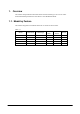
1. Overview The features and specifications described in this reference manual give an overview of the functional detailed specifications of the DT-X7 series handheld terminal. 1.1. Model by Feature The features integrated in each model of the DT-X7 series are shown below. Table 1.
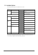
1.2. Available Options The following dedicated options are available for DT-X7 series. Table 1.2 Option Cradle Product USB Cradle Ethernet Cradle Dry-cell Battery Case Battery Battery Pack Large-capacity Battery Pack Battery charger Dual Battery Charger Cradle-type Battery Charger AC adaptor Others Cradle-type Dual Battery Charger AC adaptor Hand Belt Model no.
1.3. Application Development Environment Development platform • Microsoft Windows 2000 (SP2 or later release) • Microsoft Windows XP Development environment • Visual Studio .NET 2003+WindowsCE Utilities for Visual Studio .NET 2003 Add-on Pack 1 • Visual Studio 2005 • eMbedded Visual C++ 4.
2. Functions This chapter describes about detailed specifications of the functions implemented in the terminal and the options. 2.1. Basic Functions 2.1.1. WindowsCE Version 5.0 The terminal integrates Microsoft WindowsCE Version 5.0 as its operating system. Features at a glance • Easy-to-use user interface • .
Core Modules Microsoft core modules integrated in the terminal are as follows. Table. 2.1 Core OS Modules .NET Compact Framework .NET Compact Framework 1.0 Related Matters .NET Compact Framework 2.0 .NET Compact Framework 2.0 Strincg Resources OS Dependencies for .NET Compact Framework 2.
Applications - End User ActiveSync File Sync CAB File Installer/Uninstaller FLASH Update Sample Application Remote Desktop Protocol (RDP) Audio Playback Redirect Serial and Parallel Port Redirect Remote Desktop User Interface Dialog Box Connection Cut/Copy/Paste Clipboard Redirect File Storage Area Redirect Filtered File Storage Area Redirect PNP Notification USB Human Input Device (HID) Class Driver USB HID Keyboard and Mouse USB HID Keyboard Only USB Host Support USB HID Mouse Only Core OS Services USB
Server Communication Services and Networking Network - Local Area Network (LAN) Network - Personal Area Network (PAN) Network - Wide Area Network (WAN) Fonts File Systems and Data Store Network Functions System Password Database Support File system - Internal Duplication of File and Database Registry Storage Area Compression Storage Area Manager Courier New Tahoma Times New Roman Wingding Simple Network Time Protocol (SNTP) SNTP Client With DST Web Server (HTTPD) Core Server Support Native Wi-Fi WL
International Internet Client Services Internet Client Services Local Service Support for Languages (NLS) Input System Manager (IMM) Pocket Internet Explorer HTML View (WEBVIEW) Internet Explorer HTML/DHTML API Internet Explorer HTML Application Internet Explorer Theme Library Internet Explorer Plug In Image Decoder API Internet Explorer PNG Image Decoder Filter and Translation Internet Explorer RPC Support Internet Explorer TV Style Navigation Customizable Font Range Internet Explorer 6.
Multimedia Technologies Security Shell and User Interface Waveform Audio Audio Compression Manager Audio GSM 6.
Shell and User Interface User interface Quarter VGA Resource Longitudinal Mode Control Panel Applet Software Input Panel Software Base Input Panel (SIP) SIP for Small Screen Software Base Input Panel Driver Network User Interface Shared Control Shared Control Shared Dialog Support 16
2.1.2. Displays Basic Specifications The QVGA (320 x 240 dots) mode is supported for the terminal. The control panel can be used to switch between the VGA and QVGA modes, and the switching the display mode is initiated when a reset is performed. Table. 2.2 Display specification Display size X direction Y direction 65,536 colors 2-way TFT (16 bpp, Red: 5 bits, Green: 6 bits, Blue: 5 bits) 240 dots 320 dots Backlight brightness A brightness of the backlight can be changed in the control panel.
Backlight Auto Dimming The control panel can be used to set up whether or not the auto dimming function will be used and the waiting time until when dimming begins. Auto dimming is enabled only when the power is provided by the lithium-ion battery pack. It will not function when an external power supply is used.
2.1.3. Keys Keyboard Layout The following is the keyboard layout employed in the DT-X7. Fig. 2.
Key Assignments The following are the key codes and functions assignments. Table. 2.3 Control keys KEY Input mode Operation ---- Specialized key operation (toggle) Remarks Fn mode is released when a key input is Fn made. Character input mode CLR 1 Deletes 1 character to the left. A Deletes 1 character to the left. a Deletes 1 character to the left. P Deletes 1 character to the left. Function mode F Perform as “ESC operation”. Character input mode 1 Perform as “Enter key”.
Table. 2.4 Trigger key KEY Input mode Operation 1 Center trigger Character input mode A a P Function mode F Remarks Perform as “Trigger key”. Perform as “Trigger key”. Perform as “Trigger key”. Perform as “Enter key”. Perform as “Trigger key”. Table. 2.5 Ten key KEY Input mode Character input mode 0 Operation 1 Perform as “0”. A Perform as “-_/^\&=+$%#* space”. a Perform as “-_/^\&=+$%#* space”. P Perform as “0”. Function mode F Display or not display SIP.
Character input mode 7 Function mode 1 Perform as “7”. A Perform as “PQRS”. a Perform as “pqrs”. P Perform as “7”. F Initiate application registered in the registry below. [HKEY_LOCAL_MACHINE\HARDWARE\DEVICEMAP\KEYBD] Fn7LaunchPaht:sz (path of the application to be initiated) Character input mode 8 Function mode 1 Perform as “8”. A Perform as “TUV”. a Perform as “tuv”. P Perform as “8”. F Initiate application registered in the registry below.
Key Input Mode Switchover The A key on the keyboard can be used to change the key input mode. Indication of Key Input Mode Key input mode currently specified appears in the task tray. The modes that can be displayed are “L” as Lock, “F” as function, “1” as numeral, “A” as alphabets in uppercase, “a” as alphabets in lowercase, and “P” as telephone. L F 1 A a P Fig. 2.
Enabling or Disabling Fn Key For keys that perform specialized operations while the key input mode has been set to Function mode, “Enable” or “Disable” can be set on each individual key in the registry below to control the operations. [HKEY_LOCAL_MACHINE\HARDWARE\DEVICEMAP\KEYBD] Or, using the SysSetFnKeyOperation and SysSetFnKeyOperation functions of either Common Device Control Library or Common Device Control Class Library can achieve the same control operation explained above. Table. 2.
User Settable Keys • Initiating application The following registry can be used to assign any application to the Fn+7, Fn+8 and Fn+9 keys. [HKEY_LOCAL_MACHINE\HARDWARE\DEVICEMAP\KEYBD] Table. 2.
2.1.4. Audio Basic Specifications WAV playback, voice recording and playback are supported. When headphones are being used, playback from the speaker is halted. Stereo data is converted into mono data and then output. By using the Microsoft SoftwareMixer function, output sounds from multiple applications can be mixed and output (in 44.1 KHz, 16-bit stereo mixing).
2.1.5. Buzzer Basic Specifications The buzzer can be used to output various sounds such as scanning confirmation, alarm, warning and any other available sounds. The sounds have the following four attributes and default values. Table. 2.
2.1.6. Memory Management RAM The integrated RAM has a total capacity of 64 Mbytes and is used for the following purposes. • Program memory to be used by the OS and programs. • Object store used for temporary file saving, etc. • Other program and OS resident areas beyond the control by the OS • Driver work area The user can make unrestricted use with the object store, but data stored in it may be lost due to battery exhaustion, etc.
2.1.7. LED Basic Specifications There are two LEDs integrated in the terminal, one for the user notification on the right and the other for charging the battery complete on the left. Table. 2.
Bluetooth Connection Status This is used for notification of Bluetooth connection establishment status which is controlled by use of the Common Device Control Library. Table. 2.15 Specifications Operation mode Bluetooth established Specification ON in blue for 1 second, OFF for 2 seconds Attribute L_BT Note: Indication for scanning a bar code has the priority over other indications.
2.1.8. Vibrator Basic Specifications The vibrator can be set up for five different occasions. Table. 2.18 Occasion Alarm Warning Barcode scan complete Wireless incoming signal User definition Vibration Pattern Default Default Default Default User Setting ON or OFF ON or OFF ON or OFF ON or OFF ON or OFF Default OFF OFF OFF OFF OFF Vibration Interval The vibration interval can be set in two different patterns, the default setting and a user defined setting. Table. 2.
2.2. Scanner 2.2.1. Basic Specifications The following industrial standard bar code symbologies are supported by the laser scanner. Table. 2.
Notes: 1. MSI check digit One of the three following MSI check digit calculation methods can be selected. 1 digit, mod10 2 digit, mod10 and mode11 2 digit, mod10 and mod10 2. IATA check digit One of the three following IATA check digit calculation methods can be selected. Calculate number other than end 1 digit Calculate coupon number and numeric value segment Calculate numeric value segment 3. Minimum digit on Code39 symbology The no.
2.2.2. Scanning Method The laser scanner has “scanning state” (emits laser beam to read a bar code) and “standby state” (scanning is halted and in standby state). These two states are controlled to start scanning bar code and stop the scanning. Table. 2.22 Scanning methods Scan method Single scan Continuous scan (controlled with trigger key) Continuous scanning (controlled by program) Description Conditions for scanning to end Press the trigger key to start scanning.
2.2.3. Scanning Parameters Conditions that allow scanning a symbology in specific modes can be set for each readable symbology. Readable Symbology Bar code symbologies that are enabled or disabled for scanning can be specified. If only specific symbologies are to be scanned, set “Enable” for scanning on these symbologies only and “Disable” on the other symbologies. This will reduce decode processing time and lower the error rate. The default is “Enable scanning on all the symbologies”.
Validation Validation is carried out for a specified number of times in the range of 1 to 9 (Default = 3) to check if scanned data is valid, and then the data is output only if it is valid. The number of validations can be set either at the control panel or using the Common Device Control Library. No. of Scanning Times In “Continuous Scanning” mode, scanning continues for the preset number of scanning times in the range of 1 to 9 (Default = 1) and then it will stop in waiting mode.
2.2.4. Scanning Output Format Formats for outputting results of scanned bar codes can be set. Table. 2.24 Output Formats Symbology Standard No. of Output Format digits JAN-13 13 FFMMMMMNNNNNCT EAN-13 13 FFMMMMMNNNNNCT Remark T : Termination code JAN-8 8 FFMMMNCT EAN-8 8 FFMMMNCT See Table 2.26 for meaning of the JAN-13 15 FFMMMMMNNNNNCAAT notations.
UPC-A 14 UPC-E (7),8 UPC-E UPC-E (note 1) Code39 NW-7 00SMMMMMNNNNNCT GTIN 0MMNNNMCT Last M: 0 to 2 (7),8 0MMMNN3CT (7),8 0MMMMN4CT (7),8 0MMMMMNCT Last N: 5 to 9 (6),7 MMNNNMCT Last M: 0 to 2 (6),7 MMMNN3CT (6),7 MMMMN4CT (6),7 MMMMMNCT Last N: 5 to 9 14 0000000MMNNNMCT GTIN Last M: 0 to 2 14 0000000MMMNN3CT GTIN 14 0000000MMMMN4CT GTIN 14 0000000MMMMMNCT GTIN Last N: 5 to 9 UPC-E (9),10 0MMNNNMCAAT Last M: 0 to 2 addon+2 (9),10 0MMMNN3CAAT (9),10 0MMMMN4CAA
1 to Max Code93 See Table 2.31 for meaning of the notations Code128 Code128 MSI EAN128 1 to Max AAA ------ AAAT 1 to Max SBBB ----- BBCST See Table 2.32 for meaning of the 1 to Max AAA ------- AAAT notations 1 to Max SBBB ------ BBCST See Table 2.33 for meaning of the 1 to Max FAAA ------ AAAT notations. 1to Max GAAA ------ AAAT 1 to Max DDD ------ DDCCT See Table 2.34 for meaning of the notations. 1 to Max IATA RSS-14 RSS DDDDDDDDDD --------- CT See Table 2.
Table. 2.27 NW7 symbology S D C Start and stop characters (any of a, b, c, d) Data Check digit (mod 16). Becomes data if there is no check digit Table. 2.28 Interleaved 2of5 symbology D C Data Check digit (mod 10). Becomes data if there is no check digit Table. 2.29 Industrial 2of5 symbology D C Data Check digit (mod 10). Becomes data if there is no check digit Table. 2.30 Code39 symbology A B C ASCII conversion post data ASCII conversion pre data Check digit (mod 47).
Table. 2.36 RSS Limited symbology D C Numeric data Check digit (mod 10) Table. 2.37 RSS Expanded symbology D A Numeric data Alphabet data Termination Codes Select one of the following five termination codes to attach to the end of decoded data.
Output Buffer The scanner scans a bar code and outputs the scanned data using one of the following methods described in the table below. Table. 2.38 Output Method OBR buffer output (see note) Key message output Clipboard output Keyboard output Description - Scanned data is output to memory in the laser scanner driver. - Scanned data already output to the memory can be captured using the Common Device Control Library. - Scanned data can be output with the window message to the specified window handle.
Event Name The predefined event name which is issued for event notification can be changed in the registry described below. If there is no value set in the registry, the default event name, OBRScanningEvent, will be used. [HKEY_LOCAL_MACHINE\Drivers\CASIO\Laser] Table. 2.40 Key Name EventName Setting Value sz: Any name Capturing Event Factors When a notification for scanning completion is issued with “Event”, factors which made the scanning succeeded are automatically recorded.
Setting Specific Operation Unique to Code128 Symbology The terminal supports specific operations unique to the Code128 symbology that are initiated when certain conditions are met at a time of scanning a symbol of the Code128 symbology. Table. 2.41 Symbology Code128 Condition At time of scanning a symbol of Code128 that includes the FNC2 function character. At time of scanning a symbol of Code128 symbology that includes the FNC4 function character(s).
2.2.5. Scan Result Notification When scanning a bar code is completed, a notification about the scanning result can be indicated to the user with either LED or buzzer or vibration. Each indication method can be set to “Enable” or “Disable”. Table. 2.
2.2.6. Expanded Features Control on Laser Emission Width If the laser emits on bar codes located near each other, scanning may fail. By narrowing the laser beam emission width, scanning can be focused onto only one bar code, not onto the other one located near by. The laser beam emission width can be set to one of the following four modes. The Common Device Control Library can be used to set it. The default is “No control on laser beam emission width”.
Power ON with Trigger Key If the Trigger key has been set to “Enable turning on the power with Trigger key”, the power can be turned on (while the power was being turned off) when it is pressed. This function allows the user to achieve multiple operations with only one action, turn on the power → press the Trigger key → scan a bar code. This feature is a perfect idea when the user wishes to resume scanning after the power has been turned off. The default is “Disable turning on the power with Trigger key”.
Setting Gain The laser module gain setting can be switched. Switching this setting enhances scanning performance particularly for a bar code located far away from the terminal and a bar code printed in high-resolution. Operation Setting Information File The various setting values can be stored in a file and resumed. The setting file storage location and name are “\FlashDisk\System Settings\OBRDRV.ini”. If there is no such the setting file, the default values are used to initiate the scanning.
Customizing the Decoder According to the scan environment and the bar code printed material’s quality, the decoder can be customized to efficiently improve scanning performance. First, to maintain scanning performance with the normal decoding logic, perform decoding using with the decoder and if it does not succeed the decoding, customize it so that the decoding can be performed for a better scanning performance. Table. 2.
2.2.7. Power Control In order to save the power, the power will not be supplied to the laser scan module and the ASIC module for laser beam control during the laser beam is not irradiating. It will be supplied to these modules when the laser beam is to be irradiated, and turned off again when the laser beam is not irradiated.
2.3. USB 2.3.1. Basic Specifications Switching USB • Switches between USB Client (USB Function) and USB Host. • Switching between USB Client (USB Function) and USB Host is executed by a signal from the cradle. This cannot be performed in application. • Switching is not possible while a USB device is connected to the cradle and the terminal is recognizing the USB device. Switching can be performed once the USB device is disconnected.
2.3.2. COM Port COM ports used with USB are as follows. Table. 2.46 USB Function USB-MODEM COM2 COM5 2.3.3. Product ID USB product ID is as follows. Table. 2.
2.4. IrDA 2.4.1. Communication Speeds The IrDA supports the following physical communication speeds. Table. 2.48 Via IrDA protocol RAW IR SIR 9600, 19.2K, 38.4K, 57.6K, 115.2K bps 9600, 19.2K, 38.4K, 57.6K, 115.2K bps FIR 4M bps - Notes: • A speed of communication via IrDA protocol is automatically determined by negotiation with the partner device. • The maximum communication speed supported commonly by both parties (the terminal and the partner device) will be determined as communication speed.
2.5. Bluetooth 2.5.1. Basic Functions Master Establishes a connection with Bluetooth equipment in slave mode waiting for connection with the master. Slave Becomes in waiting mode for communication initiated by the master. Security, Encryption Performs security (PassKey exchange) and encryption as laid down in the Bluetooth standard. AFH Automatically or manually limits and controls radio wave frequency band to be employed in Bluetooth communication.
2.5.2. Communication Profiles The following are supported Bluetooth profiles. Table. 2.50 Function GAP (General Accessible Profile) SDP (Service Discovery Profile) Serial Profile (Client) Serial Profile (Server) DUN (Dial-Up Network) PAN (Personal Area Network) OBEX Object Push Profile File Transfer Profile Purpose Used in the substructure segment of Bluetooth communications such as device discovery, link establishment and security.
2.5.3. Security This feature supports security functions laid down in the Bluetooth standard. The Bluetooth security is divided into authentication and encryption. These are realized by the use of PassKey (otherwise known as PIN code). PassKey is a shared (common) authentication key used when forming a connection and trust relationship (bonding) with Bluetooth equipment. A maximum of 16 characters (in ASCII code) can be used, but there may be limitations on the no.
2.5.5. Communication Procedures The following are the basic procedures for using Bluetooth to communicate. Initializing Bluetooth This function initializes the Bluetooth using either the Bluetooth tool or the Common Device Control Library. It will turn ON the power to the Bluetooth module integrated in the terminal and initialize the Bluetooth protocol stack. 1. Searching a Bluetooth equipment Searches a Bluetooth equipment using the Bluetooth tool or the Common Device Control Library.
2.5.6. Communication Procedures by Profile While Bluetooth communication takes place, there is a chance that the communication link may be interrupted due to the air condition, so the retry process is always recommended in application to verify the communication. In general, it is recommended also that the retry process should be carried out in any wireless communication including WLAN if it takes place within the vicinity by other equipment using the same frequency band (“ISM” band) such as microwave oven.
2.5.7. Process after Communication Interruption With Bluetooth communication, there is a chance that the communication link may be interrupted due to the radio wave condition in air. An error occurred during the communication is detected by executing WriteFile API function or ReadFile API function, etc.
2.5.10. WakeOn Bluetooth Function The terminal in suspend mode can be put into resume mode by communication initiated by the partner Bluetooth equipment. The following is an example of putting the terminal into resume mode by Bluetooth dial up communication using a Bluetooth mobile phone. 1. Set the information for connecting with other party’s Bluetooth equipment in advance in the terminal (DT-X7) and Bluetooth mobile phone. 2.
2.6. WLAN The IEEE802.11b and IEEE802.11g WLAN is operable on the models, DT-X7M10R. The IEEE802.11b and IEEE802.11g standards utilize unlicensed 2.4 GHz ISM (Industry, Science, and Medical) frequency band, which is used for close range wireless communication. Device Name With terminal, the device name used to capture data about the WLAN driver with DeviceIoControl function is “PY55BG1”. 2.6.1.
2.6.2. Expanded Features Power ON/OFF Control The power to the integrated WLAN module can be controlled in application. Turning off the power when the WLAN module is not in use can save power, prevent line congestion and allow the on-board use in aircraft. Operation Configuration File The operation configuration file can be used to set each default value of the WLAN settings.
2.6.3. Roaming This feature automatically switches the Access-Point located in environment where two or more Access-Points with the identical SSID code exist. 1. Searches for Access-Points that can be communicated with the terminal, and lists up radio wave status of each Access-Point. 2. Compares radio wave status of the currently connected Access-Point with those for the listed Access-Points. 3.
2.6.4. Zeroconfig This feature coordinates with the module firmware and the WLAN driver to perform some of the WLAN link management and the Network management. 1. If multiple SSIDs are registered as prioritized connections, attempt to establish connection will be performed to each registered SSID. In this case, the interval of time period for reconnecting will become prolonged. If the reconnection time is considered to be as importance, register one SSID only as prioritized connection. 2.
2.6.5. Channels The factory set default channels is set to “1CH-13CH” (13 channels). 2.6.6. WLAN Setting with Configuration File The configuration file can be used to set the default values for the WLAN settings. By loading the configuration file into the terminal, settings required for WLAN operation can be easy. • The configuration file is “\FlashDisk\System Settings\WLANCFG.ini”. • If no configuration file is available, WLAN operation is initiated with the default settings.
File Format File format of the configuration file is INI format with the specifications described below. • The maximum size of the configuration file is 60Kbytes. • A line starting with “;” is regarded as a comment. It is not regarded as a comment if it locates in the middle of a line. • The separator for KEY and VALUE is “=”. Space and tab, etc., also are included in KEY and VALUE. If a space is inserted after “=” in “SSID=□tunami”, the SSID value is space + tunami. • The end of a line is CR or CR/LF.
TCIP section This is for setting the integrated WLAN module’s IP address. Table. 2.55 Key DHCP IPADDRESS SUBNETMASK DEFAULTGATEWAY DNS1 DNS2 WINS1 WINS2 Setting Value Specify “Enable/Disable” on the DHCP. 1: Enable DHCP. 0: Disable DHCP. The following settings are disabled if “Enable” is specified. Specify IP address. Specify subnet mask. Specify default gateway. Specify primary DNS server address. Specify secondary DNS server address. Specify primary WINS server address.
[TCPIP] DHCP=0 IPADDRESS=192.168.1.100 DEFAULTGATEWAY=192.168.1.100 SUBNETMASK=255.255.255.0 DNS1=192.168.1.101 DNS1=192.168.1.102 WINS1=192.168.1.103 WINS2=192.168.1.
2.7. Power Control 2.7.1. Low Voltage Monitoring Four levels of the low voltage monitor control are provided for the terminal. Table. 2.56 Level VDET1 Description Warning against low voltage of the battery pack VDET2 Turning off the power due to low voltage of the battery pack Emergency turning off the power due to low voltage of the battery pack Turning off the power due to low voltage of card VDET3 VDETCF Action Issues warning message for low voltage of the battery pack Turns off the power.
Memory Backup Battery The following shows levels available for the memory backup battery. Table. 2.58 Level Notation 1 O.K. 2 Almost exhausted Description The memory backup battery has been fully charged or has a sufficient capacity. The memory backup battery is in abnormal state.(10%以下) 2.7.2. Power ON Factors The followings are the power ON factors. These factors can be set enabled or disabled using the Common Device Control Library. • The Power key is pressed while the power is off.
2.7.3. Power OFF Factors The following are the power OFF factors. • The Power key is pressed while the power is on. • Neither key input, disk access, card access, nor communication is performed within a preset time period. • Output voltage from the battery pack is low (VDET2, VDET3) (see note). • The battery cover lock is open. • An excess of load on the CF card lowers voltage (VDETCF) (see note). • Internal temperature in the terminal exceeds over 70 ºC.
2.7.4. Power Saving Idle The power will be saved by putting the CPU into idle state when event standby status is detected by either the terminal or an application running on the terminal. The peripheral devices are running while the CPU is in the idle state. APO (Auto Power OFF) The power is automatically turned off when the state of no key input, no disk access, no card access, or no communication, etc., is detected within a preset time period.
2.7.5. CPU Power State Control The following shows the power states operable on the terminal. Table. 2.62 State Discharge RTC backup SLEEP mode RUN mode POWERSAVE NORMAL TURBO AUTO IDLE mode DeepIdle Contents State in that the battery pack has been discharged, and the super capacity has been also discharged. Neither RAM nor RTC will be backed up. State in that only the RTC is being backed up. RAM is not backed up.
Discharge Operating/Memory backup battery insertion Memory backup battery empty RTC backup SLEEP mode Operating battery empty Power ON Power ON Power OFF WakeUp VDET2/3 Battery Cover open RUN mode Mode Turbo Power save Normal NORMAL TURBO No activity POWERSAVE Interrupt IDLE mode DeepIdle Fig. 2.
2.7.6. Charging, Supplying the Power The optional Dual Battery Charger (HA-F32DCHG) can be used to charge battery packs (two at a time). Mounting the terminal on the USB Cradle (HA-F60IO) or on the Cradle-type Charger (HA-F30CHG) or on the Ethernet Cradle (HA-F62IO) allows charging the battery pack installed in the terminal and supplying the power to the terminal.
2.7.7. Temperature Control If temperature rise is detected in the terminal when running at the highest clock frequency (under such the condition that the CPU speed at “TURBO”, the integrated WLAN module in active mode, etc.), a warning message stating that “An error occurs !! Original reference cannot be found” appears and the power is turned off to protect the integrated devices in the terminal. Fig. 2.
2.8. Security 2.8.1. Setting Password for Terminal This is the password setting implemented in the WindowsCE OS. A password can be set at the control panel. 2.8.2. Setting Password for Date and Time Properties This is to enable setting a password for accessing the date and time setting in order to prevent the user from changing the settings of the terminal. Use PASSTOOL located under Windows folder to make the setting. Password registered will be saved in the FlashROM along with individual ID setting, etc.
3. Application This chapter explains about applications available in the terminal. They are classified into several groups described in the table below. Table 3.1 Classification Control Panel Applets Application programs Utilities Host applications Description Start up the applets at the control panel. The applets are used to set the parameters required for the terminal and integrated devices. Start up applications by accessing the menus in order of Start → Program.
3.1. Control Panel Applets The control panel applets are programs that display each content of the various parameters for the terminal itself and change the settings. The control panel applets are as follows. Table 3.
Input Panel Brightness WLAN Settings Changes the current input method and options. Changes the backlight brightness. Sets up the WLAN’s operation.
3.1.1. Bluetooth Connection This applet executes connection establishment with other Bluetooth device. For detailed explanation on the Bluetooth settings, refer to the DT-X7 series Bluetooth Setting Manual available separately. Fig. 3.
3.1.2. WLAN Power This applet is to set up the settings for power to a CF card or the integrated WLAN module (DT-X7M10R and DT-X7M10R-CN models only) and to display the detected status on the power. Fig. 3.2 CF/WLAN Power Enable Detected Set up the checkbox enabled (see Fig. 3.2) to supply the power to the integrated WLAN module.
3.1.3. WLAN Settings This applet is to set up the settings for WLAN connection. CASIO WLAN Setting Tool The tool of WLANConfig starts up by displaying the WLAN settings stored in the “ini” file if it exists in the terminal, or the default WLAN settings if it does not exists, and then displays IP Setting tab as shown in Fig. 3.3. IP Setting Tab Fig. 3.3 Basic Setting Tab This tab sets up SSID and Security. Click the radio button of Authentication to enable “Open” for WEP.
Search Button This button invokes the NetSearch utility. Security, Authentication Fields Select one of the three radio buttons in the Security field. By clicking the WPA radio button, authentication in either PSK, EAP-PEAP or EAP-TLS can be set up. If PSK is selected in Authentication, input a key in the Key field to register. See Fig. 3.5. Fig. 3.5 If EAP-PEAP or EAP-TLS is selected, user name, domain validate server, etc. can be set up. Fig. 3.
WLAN Setting Tab This tab sets up the basic WLAN settings such as power to the WLAN module, power save mode, WLAN standard and the threshold level (RSSI level) of roaming. Fig. 3.7 Detail Setting Tab This tab sets up the detailed settings. It allows to set up which application, either “NetSearch” or “NetUI”, to be used to set up for the display of WLAN condition. “NetUI” is a tool from Microsoft.
Advance Setting Button This button (see Fig. 3.8) displays a window of Advance Setting shown in Fig. 3.9. The window sets up frequency channels from no. 1 to no. 14 used in WLAN operation and the detailed settings for the roaming. Fig. 3.9 Version Button This button display the version information about the application currently running. Fig. 3.
If OK button in Fig. 3.10 is clicked, “Inifile Save Options” screen in Fig. 3.11 appears. This screen is to save the settings you made on each tab of Basic Setting, IP Setting, WLAN Setting, and Detail Setting of the WLANConfig tool. Cliking OK button in Fig. 3.11 will save the settings made on the four tabs to the ini file, and then start up the terminal to run in WLAN operation. Or, clicking Cancel button saves the settings to the ini file, but does not start up the terminal.
Wireless Information Tab (the tool from Microsoft) This tab displays a list of networks (SSID codes) connectable to the terminal and the current network being connected and the radio wave signal strength. See Fig. 3.12. Fig. 3.12 Double click a network highlighted on the screen you wish to display the Wireless Property screen. Connect Button This button displays the Wireless Property to set up the parameters required to connect the terminal with the Access-Point. Advanced...
Wireless Properties Screen Fig. 3.13 Network name (SSID) This field is to specify a network (SSID) name. This is an ad hoc network Set the checkbox enabled to communicate in AdHoc mode. Note, however, that the AdHoc mode is not recommended because a communication difficulty may occur. Encryption Using the pull-down menu, set Encryption to either “Disabled” or “WEP”. When “WEP” is selected, specify the appropriate items in the fields listed below and set the checkboxes enabled or disabled as needed.
Connection Setting Screen IP Address Tab Fig. 3.14 Obtain an IP address via DHCP Set this radio button enabled if the DHCP server is used. Specify an IP address Set this radio button if an IP address is specified directly without using the DHCP server. In this case, enter codes in each field of IP Address, Sub Net Mask and Default Gateway. Name Servers Tab This tab is to specify Primary DNS, Secondary DNS, Primary WINS and Secondary WINS as required. Fig. 3.
Advanced Wireless Settings Screen Fig. 3.16 Use Windows to configure a network Enable (set to on) this checkbox if Windows is used to configure the network settings. In this case, specify the appropriate items in the fields listed below and set the checkbox enabled or disabled as needed. See Fig. 3.16.
3.1.4. CPU Speed This applet is for setting the CPU operating mode. Fig. 3.17 TURBO This mode sets the CPU frequency to 416MHz. Note: This mode is disabled when the automatic power save mode has been set enabled. STANDARD This mode sets the CPU frequency to 208MHz. Note: This mode is disabled when the automatic power save mode has been set enabled. POWER SAVING This mode sets the CPU frequency to 104MHz. Note: This mode is disabled when the automatic power save mode has been set enabled.
3.1.5. PC Connection This tab is to set connecting method with PC. Fig. 3.18 Enable direct connections to the desktop computer Set the checkbox enabled to establish a connection in ActiveSync with PC via USB Cradle. Change Connection … Button This button displays a window (Change Connection) to change the method of connection method with PC. To set the connection establishment with PC in ActiveSync via USB Cradle, select USB Default in the pull-down menu. Fig. 3.
3.1.6. USB Connections Enabled This applet displays connection establishment of the terminal with PC or other device in USB mode. Fig. 3.20 Can be connected to PC message will appear in the tab (see Fig. 3.21) when the terminal is connected to PC in USB Client mode (USB Function mode). Or, Can be connected to LAN or modem message will appear when the terminal is connected in USB Host mode. 3.1.7. Remove Programs This applet is used to delete installed programs in the terminal.
3.1.8. Internet Options This applet is to set up Internet Explorer options. Refer to the descriptions below about the fields and the buttons in the tab. General Tab Fig. 3.22 Start Page This field is to specify the start page of URL. Search Page This field is to specify URL used with search page. User Agent This field is for selecting user agent. Start in full screen mode Set the checkbox enabled to display the full screen when the Internet is initiated a next time.
Connection Tab Fig. 3.23 Use LAN (no autodial) Set the checkbox enabled to connect the terminal in LAN mode. Autodial name Select an autodial name in the pull-down menu when communication is made without the use of LAN. Access the Internet using a proxy server Set the checkbox enabled when a proxy server is used for accessing to Internet. In this case, specify the appropriate items and value in the fields below as needed.
Security Tab This tab is to set up security by zone for Internet, Local intranet, Trusted sites and Restricted sites. See Fig. 3.25. Fig. 3.24 Sites... Button This button displays the site adding screen to enable adding the specified site specified in Add this web to the zone field to the selected zone. Settings... Button This button displays advanced setting screen for detail security setting by zone.
Privacy Tab Fig. 3.25 Privacy level This pull-down menu is to select a privacy level. Default Button This button returns the setting contents to the default values. Advanced Button This button displays the advanced privacy settings screen to set advanced settings of the privacy. Sites Button This button displays the per site privacy actions screen to set privacy by site.
Advanced Tab This tab is for setting “Enabled” or “Disable” for each parameter of the Internet Options as required. Fig. 3.
Popups Tab Fig. 3.27 Block popups Set the checkbox enabled to disable popup windows. Exceptions... Button This button displays the popup exceptions screen to set up sites to be exempted from blocking popup windows. Advanced Button This button displays the popup filter screen to set up advanced settings of the popup block. Display notification when a popup has been blocked Set the checkbox enabled to display a notification when the popup has been blocked.
3.1.9. Keyboard This applet is for setting parameters concerned with operations by the keyboard. Repeat Tab Fig. 3.28 Enable character repeat Set the checkbox enabled to set repeating key entry. Repeat delay This adjustable slide is to set a waiting time period until when repeating key entry starts. Repeat rate This adjustable slide is to set an interval between repeating key entries.
3.1.10. System This applet is used for displaying and setting parameters concerned with the internal system of the terminal. General Tab This tab displays OS version, integrated CPU name and available RAM size. Fig. 3.29 Memory Tab This tab is for setting proportional memory allocation between “Storage memory” and “Program memory”. Fig. 3.
Device Name Tab Fig. 3.31 Device name (without spaces) This field is for setting device name for the terminal itself. Spaces within the device name entered in the field are not allowed. Device description This field is to enter text string for the device description. Copyrights Tab This tab is for displaying the OS copyright information. Fig. 3.
3.1.11. Terminal Server Client Licenses This applet is used to display Terminal Server authentication licenses for client. Fig. 3.33 Stored Licenses This field is for specifying Terminal Server authentication licenses for client. Delete Button This button deletes a specified Terminal Server license. Save... Button This button saves a specified Terminal Server license.
3.1.12. Dialing This applet is for setting telephony. Fig. 3.34 Location This pull-down menu is to select telephony information to be set. New... Button This button creates a new call location. Remove Button This button removes a call location. Area code This field is to specify an area code. Country/Region This field is to specify a country or regional code. Tone dialing/Pulse dialing These radio buttons are to select a line type.
dial This pull-down menu is for specifying dial that disables the call waiting function. Edit... Button This button displays the edit dialing patterns window to set up the following dialing patterns.
3.1.13. Network and Dial-up Connections This applet is for setting connections used by dial up and LAN. The following connection types can be created. Table 3.3 Type Dial up connection Cable connection Virtual private network (PPTP) Virtual private network (L2TP) PPPoE (PPP over Ethernet) Description Establishes network connection via phone line or ISDN line. Establishes network connection with the terminal via cable (IrDA, Bluetooth included).
Establishing a new connection 1. Specify name in Type a name for the connection field and select a type of connection and then click Next > button. See Fig. 3.39. Fig. 3.36 Setting modem information 2. Set the modem information in the modem screen and then click Next > button. Fig. 3.
Setting phone number 3. Set all information about a phone number and then click Finish button. Fig. 3.
3.1.14. Version Info This applet is used to display each version number of the OS, boot section, loader and service pack integrated in the terminal. Fig. 3.
3.1.15. Vibrator This applet is to set up vibrator settings. Enable each checkbox in Fig. 3.43 (Alarm, Warning, Scan, Wake on LAN, User) to set up the vibrator function enabled for the selected events. Fig. 3.
3.1.16. Password This applet is to set up a password that is used when the terminal starts up. Fig. 3.41 Password This field is for entering the password. Only numerals can be used for the password. Confirm password This field is for entering the same password again specified in Password field for confirmation purposes. Enable password protection at power-on Enable the checkbox if password input is required when the terminal starts up.
3.1.17. Power This applet is for setting the power management options. Battery Tab This tab displays the current status of battery pack (Operating battery) and memory backup battery (Backup battery). Fig. 3.
Schemes Tab Fig. 3.43 Power Schemes This pull-down menu is to select the power source from either “Battery Power” or “AC Power”. Switch state to User Idle This pull-down menu is to set up a time period until when the terminal changes its state to User idle. Switch state to System idle This pull-down menu is to set up a time period until when the terminal changes its state to System idle.
Device Status Tab This tab displays device power levels for the integrated devices. Fig. 3.
3.1.18. Buzzer This applet is to set up “Enable or Disable” for buzzer sound and its sound volume in one of the three grades (minimum, medium, or maximum) for each event listed in Fig. 3.48. Setting on the sound volume can be checked by clicking the triangle button for each event. Fig. 3.
3.1.19. Volume & Sounds This applet is to set up “Enable or Disable” for sound types for each event listed in Fig. 3.49. Use the slide to adjust the sound volume for all the events. Enable the checkbox of event you wish to set up the sound enabled. The radio buttons are to set up either “Soft” or “Loud” for the event sounds. Volume Tab Fig. 3.46 Sounds Tab This tab is for setting the sound file that the terminal uses. Fig. 3.
3.1.20. Mouse Double click the grid in the right side of the upper screen to calibrate the double click speed and its interval. The set value can be checked by double clicking the icon in the right side of the lower screen. See Fig. 3.51. Fig. 3.48 3.1.21. Scanner Setting This applet is to change the settings for the integrated laser scanner. For detail about each parameter, refer to Chapter 2.2 “Scanner”. Read barcode Tab This tab is for specifying bar code symbologies to scan.
Driver Mode Tab This tab is to set up “Enable or Disable” for scanning each symbology of the symbologies listed in Laser Setting tab and its parameters listed below. - Min (No. of read digits) - Max (No. of read digits) - Output format - Check-digit - Check-digit output Fig. 3.
Read operation, Read operation 2 Tabs These tabs are to set up the following parameters related to scanning the bar code symbologies. Select a mode you wish to set up in each pull-down menu. - Scanning mode - Laser beam swing angle mode - Laser focus - Output buffer - Termination code - Decode level - Scanning method - Filter - Verification - Scanning - Timeout - Filter start time - Gain - Learning Decode Fig. 3.51 Fig. 3.
Notification Tab This tab is to set up notification methods selecting from the listed methods below. The notification is issued when scanning a bar code is complete. - LED light up - Buzzer sound - Vibration Fig. 3.53 Scanning Key Tab This tab is to set up “Enable/Disable” for each key of the keys listed below as the scan trigger key. - Left Trigger - Right Trigger - [L] Key - [R] Key - [U] Key - [D] Key - Center Trigger - Gun Grip Key (Trigger Grip’s lever) Fig. 3.
Others Tab Fig. 3.55 Calibration Button This button displays the OBR calibration screen to set up the calibration of laser beam swing angle. Follow the guidance appeared on the screen to complete the calibration. Restore default setting Button This button resets setting contents and restores all the settings to the default settings. Get logdata Button This button captures log information for both the scanner and decoder units. The following are the log file names. Scanner unit: “\ObrLog.
3.1.22. Display This applet is for setting color scheme for the background and desktop (appearance). Background Tab Fig. 3.57 Image Select an image to be displayed in the ground in this pull-down menu. Browse Button This button displays the file reference dialog screen to specify an image to be displayed in the background. In the dialog screen, specify a file name in Name field and its file format in Type field.
Appearance Tab Fig. 3.58 Scheme This pull-down menu is for selecting a color scheme of the desktop. Save.... Button This button saves the specified color scheme. After pressing the button, a dialogue window to confirm the specified color scheme appears. Press OK button to save it. Delete Button This button deletes the specified color scheme in Scheme field. Apply Button This button applies the specified color scheme immediately.
3.1.23. Storage Manager This applet displays the FlashDisk information. Fig. 3.
3.1.24. Owner This applet is for setting information related to the owner. Identification Tab Fig. 3.60 Name This field is for specifying the owner’s name inputting alphabets from the Input Panel appeared at the lower part on the screen. Company This field is for specifying company name of the owner. Address This field is for specifying address. Work phone This field is for specifying a phone number at work. Home phone This field is for specifying a phone number at home.
Notes Tab Fig. 3.61 Notes Using this field, a memo can be freely written. Display owner notes Set the checkbox enabled to display the note written in Notes field when the terminal starts up.
Network ID Tab Fig. 3.62 User Name This field is for specifying a user name to be used when accessing to network source. Password This field is for specifying a password to be used when accessing to network source. Domain This field is for specifying a domain to be used when accessing to network source.
3.1.25. Certificates This applet is used for editing certificates trusted by the user. Select certificate type from either Trusted Authorities, My Certificates, or Other Authorities in the pull-down menu. Fig. 3.63 Import... Button This button displays the import certificate or key screen to enable import of certificate or key. View... Button This button displays the properties of certificate or key. Remove Button This button removes certificate or key.
3.1.26. Regional Settings This applet is for setting display method and format of region, numeric value, currency, date, and time. Region Tab Fig. 3.64 Your local This pull-down menu is to select your local region. Customize… Button This button displays the number tab to enable various regional settings such as number, currency, date and time. Language Tab This tab displays language for locale selected in Region tab. The language field in this tab is grayed. Fig. 3.
Input Tab Fig. 3.66 Set the checkbox enabled in Installed Input Languages field for prescribed language to make selection.
3.1.27. Date and Time This applet is for setting date, time and time zone. Input of password may be requested if it has been set with the password tool. Fig. 3.67 Apply Button This button applies all the settings made in this tab.
3.1.28. Input Panel This applet is for changing the current input method and options. Fig. 3.68 Current input method This pull-down menu is to select an input method. The input method selected in this pull-down menu will become the default for the input panel. Options... Button This button displays the soft keyboard options screen for the input method selected in Current input method pull-down menu.
3.1.29. Brightness This applet is for setting brightness for the power source provided by either battery or external power source, the backlight auto dimming, and the backlight auto off. Brightness (Battery) Tab Fig. 3.69 Battery Power Operation This slide is for specifying brightness in one of nine grades while battery pack is being used as the power source. Auto display dimming This slide is for specifying brightness in one of eight grades when the auto brightness dimming mode starts up.
Brightness (External) Tab Fig. 3.70 External Power Operation This slide is for specifying brightness in one of nine grades while an external power supply is used as the power source.
Backlight Tab Fig. 3.71 Auto display dimming when using This parameter is for specifying “Enable/Disable” for the backlight auto dimming mode as well as a time period until when the auto dimming mode starts up. This setting is valid only when the power source is provided by battery pack. Turn off backlight when using The parameters are for specifying “Enable/Disable” for backlight auto off as well as a time period until when the backlight auto off mode starts up.
Version Tab This tab displays the information about the Brightness Properties. Fig. 3.
3.2. Application Programs Once application program is launched by accessing Start → Programs menus, the application’s operation menu is displayed to enable the processing. The following are the application programs implemented in the terminal Table 3.
3.2.1. Internet Explorer This application displays Web pages on the Internet and Intranet. • The IE 6.0 for Windows CE module is integrated in the terminal. • Kerberos, TLS Version 1.0, SSL Versions 2.0 and 3.0, and SGC are supported. • JScipt 5.5 conforms to ECMA 262 language specification (ECMAScipt Edition 3). Fig. 3.73 Table 3.
Table 3.6 Toolbar Configuration Function Return Description Returns to the previous. Advance Changes the display to the previous page displayed prior to returning. Update Updates the current page to the latest information. Homepage Returns to the homepage. Favorites Displays the Favorites menu.
3.2.2. TextEditor Fig. 3.74 Table 3.7 Menus in the application Menu Description File New Open … Save Save As … Recent Files Close Creates new text. Displays existing document file. Saves document file by overwritten. Saves document file with a specified name. Displays recently displayed document file names. Ends the application. Undo Cut Copy Paste Restores the previous operation. Cuts document in the selected range. Copies document in the selected range. Pastes document specified for cut or copy.
3.2.3. Explorer This application is a file management program. It can copy, transfer and delete files, create folders and delete folders. Fig. 3.75 Table 3.8 Menu in the application Menu Description File Open Opens files and folders. New Folder Creates new folders. Delete Deletes specified file and folder. Rename Changes specified file and folder names. Properties Displays properties of specified file and folder.
Date Auto Arrange Refresh Option … Address Bar Status Bar Lines up icons in order of date. Lines up icons in order of the method specified in “Arrange Icons”. Updates the list with latest information. Displays folder options screen. Switches between “Display” and “Hide” for the address bar, Switches between “Display” and “Hide” for the status bar. Favorites Add To Favorites … Organize Favorites … Back Forward My Documents Registers URLs in Favorites folder. Organizes files in Favorites folder.
3.2.4. Command Prompt This application starts up the Pocket CMD to enable operating the terminal with the DOS commands. Fig. 3.76 Table 3.9 Menus in the application Menu Description File Close Ends the application. Copy Paste Clear Screen Set Screen Buffer … Copies text in selected range. Pastes text cut or copied. Clears the screen. Displays screen for setting the screen’s buffer size. About Console … Displays version information.
3.2.5. Remote Desktop Connection This application is the RDP5.5 based remote desktop client. It can control a Windows PC remote from the terminal that is executing terminal service using the Microsoft remote disk top function. The following are the procedures. 1. Specify a Windows based PC remote from the terminal by inputting its computer name and IP address. Fig. 3.77 2. Log in with the remote PC by inputting the remote user name and password. See Fig. 3.92. Fig. 3.
3. If the log in is complete successfully, the terminal’s display shows the desktop of the remote PC. Fig. 3.
3.2.6. Voice Recorder This application records and playbacks voice sound. Move the slide bar located lower portion in the screen (see Fig. 3.102) to any position to define a playback start up position. Fig. 3.80 Table 3.10 Menus in the application Menu Description Tool Option Voice Recorder Other Sets recording/playing formats Sets up voice recorder settings. Sets up display and other settings. Slide Show display About Displays version information. View Table 3.
3.2.7. Laser Scanner Demo This application demonstrates the following scanning functions. • Automatic permission of setting readable bar code symbologies • Scanning bar codes using the Trigger key. • Displaying scanning results. Fig. 3.81 3.2.8. Laser Scanner Read After scanning a bar code by the integrated laser scanner, a result of the scanning is output. The output method for the scanning result will be defined by the settings made in “Laser Setting”.
3.2.9. Copy Devices This application copies various settings and applications installed in one terminal (master terminal) to other multiple terminals (child terminals). Contents to be copied Table 3.12 Target RAM Disk FlashDisk Registry Database Date/Time Contents All files in the RAM. All files in the FlashDisk. Select from “All”, “User” and “Display”. Inbox mail info, etc. Date/time set on the master terminal. Remarks Calibration data and OS build information are excluded.
2. The following screen will appear. Fig. 3.83 On child terminals 1. Click Receive Start button on each child terminal (if multiple terminals exist). See Fig. 3.119. Fig. 3.
2. On the child terminal side, the following screen will appear indicating the reception of data. Fig. 3.
3.2.10. FLCE This application enables the terminal to communicate with a PC with the Upload/Download utility being running. The communication is established via cradle. Input Command Line Screen Fig. 3.86 Screen During Transfer While the communication continues, the following screen will appear. Refer to Upload/Download Manual available separately for detail of the operations. Fig. 3.
3.2.11. ActiveSync This application is ActiveSync client program for communicating with a PC. 3.2.12. LAN ActiveSync This application is ActiveSync client program that uses WLAN.
3.2.13. Terminal This application is TTY and VT-100 terminal emulator. It is used for on-line service or communication with business server that requires the TTY terminal emulation or the VT-100 terminal simulation. Double click Make New Session icon to create new session. See Fig. 3.123. Fig. 3.88 Communications Tab Set session name, modem and phone number in each field in Fig. 3.124. Fig. 3.
Emulation Tab Set emulation type, code page and display settings in each field and checkbox in Fig. 3.125. Fig. 3.
3.2.14. NetSearch This application displays a list of partner stations communicable with the terminal via WLAN. • Partner stations on the list can be sorted in the order of field intensity, station name and channel. • Field intensity for the partner station currently being established with the terminal will be displayed in green. • The information appeared in the screen is updated every five seconds. • The remote station’s WLAN standard IEEE802.11b or IEEE802.
Detail Information About Partner Station The screen displays following details about the partner station. - SSID - WLAN standard - No. of channels - Intensity - Encryption - MAC address - Status - IP address - Physical Fig. 3.92 Click Log button (see Fig. 3.92) to display the detailed log of connections established. Fig. 3.
Or, click more … button (see Fig. 3.92) to display the log of IP in detail. Fig. 3.94 Or, click Signal button (see Fig. 3.92) to display the signal strength in dBm and with a yellow straight line that also indicates the signal strength in percent for the operator to judge if the signal in air is ample enough to continue the WLAN operation. Fig. 3.95 Clicking Return to List button switches the screen to Fig 3.92.
Partner Station Search Conditions Setting Screen Fig. 3.96 Search conditions Select a partner station to be searched via a way of either Only AdHoc, Only Accesspoint or Both. Search WLAN Standard Select a partner station to be searched via a WLAN standard either 802.11.b Support (IEEE802.11b standard), 802.11.g (IEEE802.11g standard) Support or Both.
3.3. Utilities The utilities listed in the table below are mainly used as a co-process or auxiliary program in user applications. Table 3.14 Utility FCHKCE Auto Setup Auto Recovery Tool Welcome Wizard Input Panel (SIP) Description Confirms a result of data upload/download. Executes automatically application at time of reset on the terminal. Performs automatic recovery at a time of full reset on the terminal. Sets up date/time and owner information. Software keyboard.
Customizing in the Registry Performances of the “Auto Setup” can be automatically customized by changing the parameters in the following registry. [HKEY_LOCAL_MACHINE\Drivers\CASIO\UTIL] Table 3.15 Key Setting Value AUTORUN sz:”1” sz:”2” SETUP sz:”1” sz:”2” sz:”3” sz:”4” FLSETUP sz:”1” sz:”2” Description Executes AutoRun.exe when an SD card is loaded. Executes AutoRun.exe when a memory card is loaded Executes Setup.exe for the memory card at a time of reset on the terminal. Executes Restore.
3.3.3. Auto Recovery Tool This utility uses the backup tool to back up system data, restore system data and automatically execute user designated applications. For data backup, data will be backed up by the backup tool. For data restoration, data will be restored by automatically executing the backup tool at a time of the terminal’s start up after a full reset has been performed. Backup The following is the backup procedure. 1. Starts up \Windows\Restore.exe. 2.
3.3.4. Welcome Wizard The Welcome Wizard sets up the following. However, each of the settings can be skipped if necessary. - Owner information - Date and time Notes: • Setting date and time can be avoided by setting a password even if a full reset takes place on the terminal. • Setting date and time must be performed when the RTC is cleared by a full reset on the terminal. Customizing Startup Screen An optional bitmap can be displayed as the Welcome Wizard startup screen.
3.4. Application The following are applications used by host PC linked with the terminal. Table 3.16 Application ActiveSync LMWIN FCHK Description Executes data link with the terminal. Executes data upload/download. Checks and confirms a result data upload/download. CASIO -Yes Yes MS Yes --- MS; Microsoft 3.4.1. ActiveSync By linking with the ActiveSync client installed in the terminal, this utility makes communication with the terminal possible. It is available from the following site. http://www.