(without price) Palm-size Personal Computer E-100 (JX-530A) E-105 (JX-530E) MAY. 1999 E-100/105 INDEX R Ver.
CONTENTS 1. SPECIFICATIONS ------------------------------------------------------------------------------- 1 2. UNPACKING -------------------------------------------------------------------------------------- 3 3. GENERAL GUIDE and INITIAL SETUP 3-1. General Guide ---------------------------------------------------------------------------- 4 3-2. Initial Setup ------------------------------------------------------------------------------- 6 4. RESET OPERATION and BATTERY REPLACEMENT 4-1.
1. SPECIFICATIONS Model: Display: E-100/E-105 240 × 320 dots TFT Color LCD (65,536 colors) CPU: VR4121 Memory: 16/32MB Interfaces: Serial: RS-232C, 115.2 kbps max. Infrared: IrDA Ver. 1.0, 115.2 kbps (max.) Range: 30 cm max. Card Slot: CompactFlash card, 3.3V Type I/Type II Headphone jack: ø 3.5 mm stereo output Accepts monaural earphone,stereo earphones,stereo headphones.
Current consumption: NOTES: 1. Be sure to measure after adjustment referring to 6.ADJUSTMENT of this manual. 2. When measuring these current, be sure to use suitable range analog ammeter. Operation Mode Main menu of OPERATION CHECK in this manual Input Rechargeable Battery : 4.0V ± 0.1V Current consumption ≤280mA 5. POWER CONTROL of OPERATION CHECK of this manual Rechargeable Battery : 4.0V ± 0.1V ≤600mA 5. POWER CONTROL of OPERATION CHECK of this manual AC Adapter : 5.0V ± 0.
2. UNPACKING Refer to 15. EXPLODED VIEW of this manual. Check to make sure that all the items listed below are included. Stylus (Inserted inside CASSIOPEIA ) • • • • CASSIOPEIA Unit • • • • Cradle • Rechargeable Battery Pack AC Adapter Soft Case Two Manuals (Hardware Manual,Palm-size PC User’s Guide) User Registration Card Microsoft Windows CE CD-ROM CASSIOPEIA CD-ROM (E-105 only) MS AUDIO CD-ROM (E-105 for U.S.A / CANADA/ for Europe & U.K. (not supplied for spare part)) AUDIBLE CD-ROM (only U.S.
3. GENERAL GUIDE and INITIAL SETUP 3-1. General Guide • Card Slot • Charge indicator(Green) Indicates battery pack is charging. • Stereo headphone jack For connection of a commercially available earphone/ headphone(ø3.5mm) • Stylus • Indicator lamp(Red) Alerts you to alarms and warning • Touch screen Perform operations and input data by tapping and writing directly on the screen. • Power button Turns power on and off. • Exit button Same as computer’s ESC key.
• Card lock switch Locks the card in the slot so it does not come out accidentally. • Backup battery cover • Main battery cover • RESET button • Battery cover switch • Serial connector Mates with the cradle connector. About the [Action] Control Operations can be performed by pressing and rotating the [Action] control. Rotating the [Action] control performs operations similar to the up and down arrow keys of a computer keyboard.
3-2. Initial Setup Perform the following initial setup procedure after repair. 1. Load the main battery (rechargeable battery pack). Be sure to use the AC Adapter to charge the rechargeable battery pack before doing anything else. Your CASSIOPEIA will not operate correctly if you load the backup battery before charging the battery pack. 1 Slide the battery cover switch to MAIN and remove the main battery cover. 2 Install the rechargeable battery pack that comes with the CASSIOPEIA.
3. Load the backup battery (CR2032). 2 After wiping both side of a new lithium battery (CR2032) with a dry cloth, place it into the battery compartment with the positive side facing up (so you can see it). 1 Slide the battery cover switch to BACK UP, and then remove the backup battery cover. 3 Replace the backup battery cover and slide the battery cover switch back to LOCK. 4. Let the CASSIOPEIA rest for about five seconds, and then press the [Power] button.
■ Full Reset (Memory Initialize) Full reset (memory initialize) deletes all data, and resets all unit parameters to their initial defaults. The following are conditions when you should perform a full reset. • • • • When you want to delete all memory data and return unit settings to their factory defaults. When you forget your password and need to clear it. When a data error causes operational problems. Appearance of the message: “A problem with memory contents has been found···”.
4. RESET OPERATION and BATTERY REPLACEMENT 4-1. Reset Operation “Reset” is similar to a computer reboot. Performing a reset deletes any data that is in the process of being input or edited, without yet being saved. Data stored in memory and all settings, however, are retained. Perform the reset operation whenever the unit fails to operate correctly due to operational error or some other abnormality. Any of the following symptoms indicate that reset is required.
4-2. Battery Replacement You CASSIOPEIA is powered by a dual power supply that consists of a main battery (rechargeable battery pack) and a backup battery (CR2032 lithium battery). • We recommend that you use the Power properties dialog to keep informed about the current levels of your main and backup batteries. See the separate Palm-size PC User’s Guide for more information about this dialog. • Icons appear in the Taskbar to let you know when battery power is low.
• Always make sure that the positive (+) and negative (–) poles of the batteries are oriented correctly. • Use only the types of batteries specified for use with this unit. • Charge the battery pack in an area where the temperature is between 10˚C (50˚F) and 35˚C (95˚F). Charging in areas that are very cold or exposed to direct sunlight can cause deterioration and leaking of the battery pack.
1. Make sure your CASSIOPEIA is turned off. • Press the [Power] button to turn off power. 2. Turn the CASSIOPEIA over. 3. Slide the battery cover switch to BACK UP, and then remove the backup battery cover. Battery cover switch 4. Remove the old battery. 5. Wipe off a new lithium battery (CR2032) with a dry cloth, and load it into the CASSIOPEIA. Make sure the positive side is facing up, so you can see it. 6. Replace the back-up battery cover. 7. Slide the battery cover switch back to LOCK.
Charging the Battery Pack 1. Install the battery pack into the CASSIOPEIA. 2. Attach the AC adapter to the cradle and place the CASSIOPEIA onto the cradle. • • • • Charging starts automatically as soon as you place the CASSIOPEIA onto the cradle. The charge indicator is green while charging is in progress. It goes out when charging is complete. It takes about five or six hours to reach full charge if this pack is entirely discharged. You can use your CASSIOPEIA while the battery pack is charging.
5. DATA TRANSFER 5-1. General There are basically four kinds of data transfers concerning E-100/105. 1. Data transfer between PC and E-100/105 using the software of Windows CE Services (Ver. 2.2) refers to Memory Backup/ Restore described in latter page concerning this transfer. 2. Data transfer between E-100/105 and Compact Flash memory card refers to Card Backup Tool described in latter page concerning this transfer. It is recommended that CF-15 (15MB)/ CF-30 (30MB) is used for this transfer. 3.
■Memory Backup / Restore Make the backup copy by Windows CE Services 2.2 to your PC before repairing E-100/105, and restore the data from PC to user’s E-100/105 after repairing. For the details of Backup/ Restore, refer to User’s Guide for the Palm-size PC . Notes: 1. Backup program of Windows CE Services 2.2 back up only files and databases. The data entered in Owner, World Clock mode and so on can not be backed up to PC. 2. Use AC adapter when making backup copy and restoring. 3.
8. Confirm the file name of back up copy (Backup.stg). Remember or record the directory which its file is backed up also. For example: C\Program File\Windows CE Service\Profiles\Guest\Backup.stg And then, after selecting OK button, Full Backup starts.
Restore Perform the following procedure for restoring after repair. 1. Turn on E-100/105. 2. After pressing Action button while holding down Power button, perform touch panel calibration on E-100/105, and then skip the other setups after calibration (Full RESET). 3. Connect E-100/105 to your PC with the cradle. 4. Window CE Services 2.2 automatically detects E-100/105 connected to PC. 5. Clicking Mobile Devices icon, starts Windows CE Services 2.2 on your PC. 6. The following screen will be displayed.
10.Detect Back up.stg file using Browse... button. After you succeed in this detection, the following screen appears. 11. Selecting OK button, the following screen will appear. 12. After selecting Restore button, the data transfer from PC to E-100/105 starts. 13. The following screen will appear after this data transfer. Finally, click OK button.
■At present, there are four kinds of Compact Flash memory cards as follows. CF-2 (2MB)/ CF-4 (4MB)/ CF-10 (10MB)/ CF-15 (15MB)/ CF-30 (30MB)/ CF-48 (48MB) ■How to save the data to Compact Flash memory card without PC (Applicable to only “Note Taker” and “Voice Recorder” mode as well as E-10/ E-15) < PROCEDURE > 1. Note Taker (1) Tap Start, and then Note Take. (2) Tap icon, Tools, Options, and then Columns. (3) Select Location. (4) Tap Save, and then select Save to storage card. (5) Tap OK.
■ User's Guide for Card Backup Tool Contents INTRODUCTION ......................................................................................................................... BACKED UP DATA .......................................................................................................... TIME REQUIRED FOR BACKUP ..................................................................................... USING CARD BACKUP TOOL ............................................................................
Introduction Card Backup Tool lets you quickly and easily back up your CASSIOPEIA memory data to a memory card. Backed up data lets you easily restore your system should it start to malfunction due to some data error. Backed Up Data Card Backup Tool backs up the following three types of data in CASSIOPEIA memory. • Files Files are created using Voice Recorder, Note Taker, and other applications and add-on programs. Files transferred from your desktop computer to the CASSIOPEIA are also backed up.
Backing Up Data Use the following procedure to back up data. Make sure you read the precautions under "Read this first!" on the previous page before starting. To back up data 1. 2. 3. 4. • Connect the AC adapter to your CASSIOPEIA. Reset the CASSIOPEIA. Insert a memory card with sufficient free space to store the backup data into the CompactFlash card slot of the CASSIOPEIA. Tap [Start], [Programs], [Utility], and then [Card Backup].
To interrupt a backup operation 1. • 2. Tap the [x] close button in the upper right corner of message box that is on the screen while a backup operation is in progress. This causes the message "Do you really want to cancel?" to appear. Tap [Yes] to cancel the backup operation or [No] to resume it. Restoring Data Performing the restore operation causes the following to happen.
5. • 6. • • 7. 8. Tap [Restore now]. This causes the dialog shown below to appear. Tab [Yes] to start the restore or [No] to close the dialog without restoring anything. An hourglass icon on the screen indicates that the restore operation is being performed. The message "Restore complete!" appears on the display after the restore operation is complete. After restore is complete, tap [OK] to quit Card Backup Tool. Reset your CASIOPEIA again. To interrupt a restore operation 1.
5-3.Infrared Communications (Quotation from the Microsoft User's Guide) Your Palm-size PC has an infrared port that you can use to exchange information with another Windows CE device. In Contacts, for example, you can send up to 25 cards at a time to another Windows CE device. In Voice Recorder and Note Taker, you can send individual files or notes. Note Taker Infrared Send Menu To transfer data with infrared 1.
6. ADJUSTMENT There are two adjustments using variable resistors (VR300/ VR301) concerning E-100/-105. Refer to Main Block (3/3) of 11. SCHEMATIC DIAGRAM of this manual. Before performing these adjustments, remove the lower case referring to 13. DIASSEBLY PROCEDURE of this manual. Set the battery cover switch to LOCK position. And then, after adding 4.0 ± 0.1V to the battery terminal, perform Full RESET. Therefore, save Use's data to PC or Compact Flash memory card before these adjustments. 6-1.
7. OPERATION CHECK 7-1. Preparation 1. 2. 3. 4. E-100/ -105 Compact Flash memory card Rechargeable battery pack AC adapter (AD-C50200) Notes: 5. Cradle 6. PC installed Windows CE Services 2.2 7. Diagnostic program (Diag. exe) ■ Be sure to make back-up copies of all important data in E-100/-105 because this check make these data deleted. ■ Diagnostic program (Diag. exe) exist in SOFT holder of CD-ROM for Service information Disk. ■ After all checks are finished, perform Full Reset.
■ Once the diagnostic program is saved to Compact Flash memory card and E-100/-105, you can perform this operation check without Compact Flash memory card because this program is saved to D-RAM memory in E-100/-105. Even if you delete this program saved to RAM memory by Full RESET and so on, you can perform this operation check after inserting this Compact Flash memory card again. ■ If you want to delete quite diagnostic program file (Diag.exe file) in Compact Flash memory card, delete Diag.
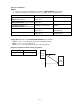
7-3. Operation Check 1. Perform 3-2. Initial Setup of this manual. 2. Install the diagnostic program to E-100/-105. 3. Tap Start, Settings, and Taskbar. 4. Select Auto hide, and then tap OK. Power 5. Press Contacts button while holding down Power button. Refer to the right figure. Contacts 6. After performing this operation, the following Main Menu appears in the LCD display. ** Main Menu ** 1 DISPLAY 2 TOUCH PANEL 3 MEMORY 4 SERIAL 5 POWER CONTROL 6 AUDIO 7 Others 8 COLOR BAR 9 CAMERA CPROG Rev.
ITEM Display OPERATION DISPLAY NOTE Tap the panel. Medium GREEN Tap the panel. Medium BLUE Touch panel Tap the panel. No display Tap the panel. All dots Tap the panel twice. Main Menu display Tap 2 TOUCH PANEL.
ITEM Touch panel OPERATION DISPLAY Tap 1Case. Case ---> OK Press Action button. ** Touch Panel ** NOTE 1 Case 2 Points 3 Cross Tap 2 Points. Tap four crosses in any order. Touch Panel -----> OK Press Action button ** Touch Panel ** NG if any crosses remain on the display after tapping all four crosses. 1 Case 2 Points 3 Cross Tap 3 Cross. Trace on the center of the two black lines in the direction shown to the right arrows.
ITEM MEMORY OPERATION DISPLAY Press Action button twice. Main Menu display Tap 3 MEMORY. ** Memory ** NOTE Main Menu for 3 MEMORY 1 ROM CHECK SUM(32MByte) 1 'ROM CHECK SUM(16MByte) 2 ROM BUS CHECK(32MByte) 2 'ROM BUS CHECK(16KByTE) 3 ROM TYPE 4 RAM TEST 5 RAM LOOP 6 RAM R/W TEST Tap 1 ROM CHECK SUM (32Kbyte). ** ROM CHECK SUM ** base addr. Sum value SUM 1 (beXXXXX) = XXXX SUM 2 (beXXXXX) = XXXX Press Action button, and then tap 2 ROM BUS CHECK (32Kbyte).
ITEM POWER CONTROL AUDIO OPERATION DISPLAY Press Action button twice. Main Menu display Tap 5 POWER CONTROL. Currently CPU clock is 131MHz Push Action key to exit Press Action button. Main Menu display Tap 6 AUDIO. ** Audio ** NOTE Refer to Current consumption of 1. SPECIFICATION of this manual. To regain this menu, press Action button. 1 0.5kHz 2 1kHz 3 2kHz 4 Record Tap 1 0.5kHz. AUDIO 0.5kHz Sound of AC 0.5kHz is emitted. After tap Action button, tap 2 1kHz.
ITEM Others OPERATION Press Action button twice. Tap 7 Others. DISPLAY NOTE Main Menu display ** Others ** Main Menu of Others 1 Switch 2 Compact Flash(CDs, CDOR) ........................... 6 BackLight Tap 1 Switch. VDET1R VDET2R VDET3 VDETS VDETCF AC Adapter Cover Charge Confirm that red LED is flickering. Remove Backup battery (CR2032). ............................................. VDETS ON ............................................. Confirm that red LED is flickering.
ITEM Others OPERATION Finally, press EXIT button. DISPLAY ** Others ** NOTE Main Menu of Others 1 Switch 2 Compact Flash(CDs, CDOR) ........................... 6 BackLight Tap 5 Disk Loop. Press Action button ** Others ** Main Menu of Others 1 Switch 2 Compact Flash(CDs, CDOR) ........................... 6 BackLight Tap 6 BackLight. 183 COLOR BAR Press UP/ DOWN keys of Cursor button. Display becomes lighter/ dimmer. And the number displayed below changes. Press Action button twice.
ITEM OPERATION COLOR BAR Tap 2 Scroll. Press Action button DISPLAY NOTE Scroll display of Color bar ** COLOR BAR ** Main Menu of COLOR BAR 1 Contrast 2 Scroll 3 GRAY Tap 3 GRAY. All gray display Refer to 6. ADJUSTMENT. ■ IrDA CHECK 1. Prepare two units. 2. Install Diagnostic program to both units. 3. Display Main Menu of Diagnostic program with both units. 4. Tap 4. SERIAL with both units. 5. Set both units to the position described to 1. SPECIFICATION of this manual (≤32cm/ ≤15˚).
7-4. New (Second) Version Diagnostic Program Rev. 0.50 Main menu display of the old (first) version Diagnostic Program for this check was as follows; ** Main Menu ** 1 DISPLAY 2 TOUCH PANEL 3 MEMORY 4 SERIAL 5 POWER CONTROL 6 AUDIO 7 Others 8 COLOR BAR 9 CAMERA CPROG Rev. 0.40 for JX-537 New (Second) Version Diagnostic Program will be supplied together with this second edition (version 1) Service Manual. “CPROG Rev. 0.40 for JX-537” in above old display will be changed for “CPROG Rev. 0.
2. Tapping 3 MEMORY, the following display appears. ** Memory ** 1 ROM CHECK SUM(32MByte) 1 ‘ROM CHECK SUM(16MByte) ................................................ ................................................ ................................................ 7 RAM special R/W TEST(32MByte) 7’RAM special R/W TEST(16MByte) 3. Tap 7 RAM special R/W TEST(32MByte) in case of E-105. On the other hand, tap 7’RAM special R/W TEST(16MByte) in case of E-100. 4.
8. TROUBLE SHOOTING Before assuming malfunction and contacting your expert when experiencing operational problems, be sure to check the following information as well as the troubleshooting section of the Palm-size PC User's Guide first. Nothing happens when the [Power] button is pressed. Possible Cause Recommended Action Main battery is weak. Charge the battery pack. Internal malfunction Reset the unit. If resetting the unit does not correct the problem, perform a full reset (memory initialize).
The low back-up battery message continues to appear even after replacement of the back-up battery. Possible Cause Recommended Action The back-up battery is upside down. Remove the back-up battery, turn it over, and reload it. The back-up battery was loaded before the main battery. Remove the back-up battery, and reload it. Power was left on while the battery pack was replaced. Turn power off and then back on again. Nothing happens when the touch screen is touched.
9. CIRCUIT EXPLANATION 9-1. BLock Diagram OSC for timer clock OSC for CPU OSB OSC for fast IrDA Control 18.432MHz 32.768kHz PLL OSB 48.000MHz Fast IrDA Control IrDA Module CORE of CPU (131MHz) Instruction/ Data Cashe Mem. Bus Control Unit Panel IF A/D Touch Panel Audio IF D/A Mic Amp.
9-2. Power Supply ■ Block Diagram of Power Supply and Voltage Detector AC Adapter (AD-C50200) 5. 5~4.7V (TYP:5.0V) 2A MAX. FUSE F200 Voltage DET. 4.1V (IC214) VCHG(6.0~6.4V) DC-DC Converter (IC207) VLION *Current DET. *Voltage DET. VDCIN Controller for Rechargeable Battery (IC303) F201 CPU Rechargeable Battery (Lithium-ion) 3.2~4.2V CUT OFF with 2.3V ON/OFF P5LCD Temperature DET. VDET1RB Low Battery Message Voltage DET. 3.4V±1% (IC200) VDET2R Forced power OFF Voltage DET. 3.
9-3. Function Refer to the 9-1. Block Diagram, 9-2. Power Supply and 11. SCHEMATIC DIAGRAMS. Boot Sequence at the time of setting Rechargeable Battery Setting Battery V3SYS Stabilization of oscillation 32KHz OSC. ≤1 sec. Waiting for turning power on ACLB 3.72 sec. Of course, if one of these three factors don’t start to boot, the unit don’t work. Boot Sequence at the time of turning power on Turning power on MPOWERB 18.432MHz OSC. Fetch Cycle to ROM POP (for 2ch DC-DC Con.
II/O Pins Configuration Table Pin Symbol Description 1 VCC Supply Voltage 2 AGND Analog Ground 3 FIRSEL FIR (Fast IR) Select 4 MD0 Mode 0 5 MD1 Mode 1 6 NC No Connection 7 GND Ground 8 RXD Receive Data Output 9 TXD Transmitter Data Output 10 LEDA LED Anode Transceiver Control Truth Table Mode 0 Mode 1 FIRSEL RX Function 1 0 Don’t Care Shutdown 0 0 0 SIR (Slow IR) 0 1 0 SIR (Slow IR) 1 1 0 SIR (Slow IR) 0 0 1 MIR/FIR 0 1 1 MIR/FIR 1 1 1 MIR/FIR 0: Low Level Voltage/ 1: High Level Voltage TX Function Shutdow
■ TFT LCD Module (COM38T3103DPQ) This module mainly consists of TFT-LCD, Back-light and DC-AC inverter for driver of Back-light.
10.
11. SCHEMATIC DIAGRAMS 11-1. Main Block (1/3) Gate Array CPU Gate Array : DRAM1 and DRAM2 only * E-100 DRAM3 and DRAM4 are not used.
11-1.
11-1.
11-2.
11-3.
11-4.
11-5.
12.
MAIN PCB (2/2) — 55 —
13. DISASSEMBLY PROCEDURE Backup battery cover Rechargeable battery ■ COMPONENTS 1. Position Battery cover switch on “MAIN” and remove Rechargeable battery cover. 2. Pull Battery removal sheet and extract Rechargeable battery. 3. Set Battery cover switch on “BACK UP” and remove Backup battery cover. 4. Remove Backup battery. Battery cover switch Battery removal sheet Rechargeable battery cover CF cover 5. Remove CF cover. Stylus 6. Pull out Stylus. screw A 7. Remove 4 screw A's. 8.
■ INNER CASE ASS'Y 1. Peel off Insulation tape (transparent). Insulation tape (yellow) 2. Utilizing tweezers, disconnect Touch panel (TP) connector. Insulation tape (transparent) TP plate screw C 3. Remove 3 screw C's and separate TP plate. Touch panel FPC sub ass'y screw D 4. Remove 2 screw D's from MAIN PCB ass'y. 5. Disconnect FFC joiner from the connector. connector 6. Disconnecting the connectors, separate LCD module and MAIN PCB ass'y. FFC joiner Inverter 7.
■ UPPER CASE ASS'Y screw E 1. Extract Microphone ass'y from Upper case. 2. Remove 3 screw E's and separate KEY PCB ass'y. KEY PCB ass'y Microphone ass'y LED covers Side key 3. Remove 2 screw F's and displace Speaker. 4. Remove Contact rubber, Buttons, and XY keys. screw F Note: Do not remove Side key (located on the side of the case) unless it needs to be replaced. 5. Remove 2 LED covers.
■ LOWER CASE ASS'Y screw G knob holder 1. Unscrew 2 screw G's and remove Reset key and CF lock knob. screw H lock knob 2. Remove 2 screw H's and separate C holder. 3. Remove 2 screws and separate knob holder and Battery cover switch.
14. PARTS PRICE LIST E-100/105 14-1.PCB ASSY, COMPONENTS and OTHERS N Item Code No.
N Item Code No.
N Item N OTHERS 63 64 65 66 67 68 69 N 70 71 Code No. Parts Name Q'ty Specification Price Code R E-100 E-105 N N N 72 73 6566 3220 BOARD/CRADLE C241325-1 1 1 3815 0822 CASE/SOFT SCJ537AA01 1 1 1001 0878 SOFTWARE/CD-ROM(MS) CDJ530AA01A 1 1 3301 0448 ADAPTER/AC AD-C50200U 3301 0468 ADAPTER/AC AD-C50200CB See to the 3301 0446 ADAPTER/AC AD-C50200G lower table. 3301 0469 ADAPTER/AC AD-C50200A Refer to the lower table concerning these four adapters (Item 66~69).
14-2. CRADLE N Item N 101 102 103 Code No. Parts Name Q'ty Specification 6670 2541 CRADLE 6670 2472 PCB ASSY/CRADLE 3335 6733 CABLE C241388*2 C241390*1 UJ0525#01-0 E-100 E-105 1 1 1 1 1 1 Parts prices will be informed separately by Parts Price List.
15. EXPLODED VIEW 15-1. PCB ASSY, COMPONENTS and OTHERS (1/3) NOTE : Don’t heap up item 5 (MAIN PCB ASSY) or put on a heavy object onto item 5 to prevent from clacks in D-RAMs. Item 17 does not be assembled onto item5.
15-1. PCB ASSY, COMPONENTS and OTHERS (2/3) NOTE : Item 22 is assembled onto the copper tape to cover and blind it.
15-1.
15-2. CRADLE *Parts of item102/103 are assembled in CRADLE.
Ver.1 : (1) Additional item 7-4.New (Second) version Diagnostic Program Rev. 0.50 to 7.OPERATION CHECK (2) Deletion of page 54 ~ 56 in the first Edition Manual (3) Additional spare part (Item 73) to PARTS LIST, Additional explanations on page 62 and Modification of Applicable models on page 62 CASIO TECHNO CO.,LTD. Overseas Service Division Nishi-Shinjuku Kimuraya Bldg.