
Specifications


— 44 —
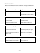
II/O Pins Configuration Table
Pin Symbol Description
1 VCC Supply Voltage
2 AGND Analog Ground
3 FIRSEL FIR (Fast IR) Select
4 MD0 Mode 0
5 MD1 Mode 1
6 NC No Connection
7 GND Ground
8 RXD Receive Data Output
9 TXD Transmitter Data Output
10 LEDA LED Anode
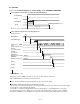
Transceiver Control Truth Table
Mode 0 Mode 1 FIRSEL RX Function TX Function
1 0 Don’t Care Shutdown Shutdown
0 0 0 SIR (Slow IR) Full Distance Power
0 1 0 SIR (Slow IR) 2/3 Distance Power
1 1 0 SIR (Slow IR) 1/3 Distance Power
0 0 1 MIR/FIR Full Distance Power
0 1 1 MIR/FIR 2/3 Distance Power
1 1 1 MIR/FIR 1/3 Distance Power
0: Low Level Voltage/ 1: High Level Voltage
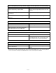
- IC M62253FP (IC303) for Rechargeable Battery Controller
II/O Pins Configuration Table
Pin Symbol Description (Function)
1 TIN Detection of temperature & connection with unit
2 C3 Terminal for setting of delay time of detection by TIN
3 Vref Reference voltage terminal for interior circuits
4 VDD 5.0V Reference voltage terminal
5 VCC Power supply voltage (= VCHG)
6, 7 LED1, 2 Terminal for connection with LED
8 C1 Terminal for setting of delay time of detection of voltage
9 C2 Terminal for setting of delay time of detection of current
10 GND Ground
11 VSENSE Terminal for voltage detection
12 SENSE- Detection terminal of charge current (low current)
13 SENSE+ Detection terminal of charge current (high current)
14 OUT Direct control to charge current from AC Adapter
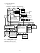
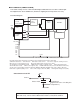
- Rechargeable Battery (Lithium-Ion Battery)
* Brief Block Diagram
CHGOUT +
CELL CHGDET
IC for protector
Thermistor
Fuse
BATGND -
There is a thermistor in Battery to prevent from overheat. Thermal detection range is 5˚~35˚ C.
If terminal voltage of CHGOUT+ is 2.3V, the charge/ recharge to CELL will be completed after about
6 hours.
Warrantee charge/ recharge times are 300 times. But charge/ recharge times can be performed more
than 300 times actually.
Using Compact Flash Memory Card frequently, this battery life will be shortened.
It is recommended that the unit is driven by AC Adapter when using this card.