Chapter 1: Getting Ready Chapter 1: Getting Ready This chapter acquaints you with CASIO Data Analyzer key operations, display indicators, and other basic information you need to know. It also tells you how to replace batteries, connect to a graphic scientific unit, and perform other set up procedures before beginning actual operation. Unpacking ............................................................................ 2 CASIO Data Analyzer Overview .......................................... 3 Keyboard ..
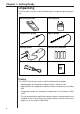
Chapter 1: Getting Ready Unpacking Check to make sure that all of the following items are present during unpacking. Data analyzer unit Carrying case Temperature probe Optical probe Voltage probe Four AA-size batteries Data communication cable User’s Guide (this manual) EA-100 Probes The CASIO Data Analyzer comes with the following three probes.
Chapter 1: Getting Ready CASIO Data Analyzer Overview The CASIO Data Analyzer is a digital instrument you can use to sample and collect data on various everyday natural phenomena. The following sections provide information on using its probes and channels, and tell you how to connect to a graphic scientific calculator. A number of other important functions of the data analyzer unit are also introduced here.
Chapter 1: Getting Ready Command and Programs There are a total of 10 commands defined for this data analyzer unit: Command 0 through Command 9. These commands can be used to specify such parameters as the type of data being sampled, the channel being used for sampling, the sample time, and the number of samples. Commands are sent from a connected graphic scientific calculator (CFX-9850G/CFX-9800G) to the data analyzer unit, which then executes them.
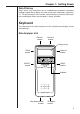
Chapter 1: Getting Ready Data Filtering Static “noise” can sometimes cause sampled data to become corrupted, making it impossible to obtain accurate results from calculations and analysis. This data analyzer unit includes a data filtering system that eliminates noise and help to make sure that data is always accurate. Keyboard The front panel of this data analyzer unit has a liquid crystal display screen and eight keys.
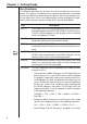
Chapter 1: Getting Ready Key Functions The following describes the functions of each of the eight keys on the keyboard. This section is intended more as a reference and contains information that may be difficult to understand at first glance. Don’t worry though, many of the expressions used in the following key function descriptions will become clearer after you read the section of this manual titled “Modes.
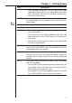
Chapter 1: Getting Ready Key Description • Data-Log Mode: Each press of [CH-View] in this mode sequentially switches the channel whose data is on the display. The channel indicator of the currently selected channel flashes on the screen. [INTERNAL] Pressing this key while in the Communications Mode enters the Internal Mode. Pressing it again returns to the Communications Mode P.35 [XMIT-9800] Pressing [SHIFT][INTERNAL] sends data to the CFX-9800G.
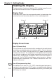
Chapter 1: Getting Ready Reading the Display The data analyzer’s liquid crystal display (LCD) is divided among five areas, each of which indicates the status of a particular operation. Display Panel The display screen shows the current operating mode, the input/output channel being used, and information about the current sampling operation.
Chapter 1: Getting Ready Area 3 (Sampling Status Area) The indicators in this area shows the current data sampling status. READY means the data analyzer is ready and standing by for data sampling, SAMPLING indicates that a sampling operation is in progress, and DONE means that the sampling operation is finished. All three of these indicators flash in the Setup Mode. Area 4 (Mode Area) These indicators show the current operating mode of the data analyzer.
Chapter 1: Getting Ready • Voltage: Less than –10V • Temperature: Less than –20°C • Light: Less than 100 Power Supply The data analyzer can be powered by four AA-size batteries or an optional AC adaptor (AD-A60024). This section tells you when you should replace batteries and how to connect the optional AC adaptor. Batteries The data analyzer can be powered by four AA-size batteries.
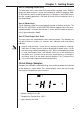
Chapter 1: Getting Ready 2. Load four AA-size batteries into the battery compartment, making sure they are facing as shown in the illustration inside the battery compartment. 3. After loading batteries, replace the battery compartment cover. 4. Press [ON/OFF] to turn on power, which should make the screen shown below appear on the display.
Chapter 1: Getting Ready • Never try to modify the power cord of the AC adaptor, do not allow it to become broken or cracked, and do not subject it to excessive bending, twisting, or pulling. Do not place heavy objects on top of the power cord and do not subject it to direct heat. Any of the above creates the danger of fire and electrical shock. • Never touch the AC adaptor while your hands are wet. Doing so creates the danger of electrical shock.
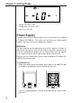
Chapter 1: Getting Ready Connecting the Data Analyzer to a Calculator The following procedure describes how to use the data communication cable that comes with the data analyzer to connect it to a CFX-9850G or CFX9800G graphic scientific calculator. Data communication cable (SB-62) 1. Turn both units off. 2. Plug one end of the data communication cable into the data communication terminal of the calculator you are connecting to. 3.
Chapter 1: Getting Ready Analog Input Channels CH1, CH2, and CH3 are analog input channels for connection of probes that measure electrical change. All three analog channels perform identical types of sampling. Ultrasonic Input Channel This channel is for connection of a distance sensor that can be used to measure the distance from the probe to an object.