(without price) BN-10 BN-20 (ZX-456) (ZX-457) NOV.
CONTENTS 1. SPECIFICATIONS ................................................................................................ 3 2. GENERAL GUIDE 2-1. Appearances and Display Indicators ....................................................... 5 2-2. Modes and Cursor Keys etc. .................................................................... 7 2-3. Backlight Operation (BN-20 only) ..........................................................13 2-4. Power Supply ...................................................
1.
Current consumption: at battery voltage = 3 V, at data transmission with MODEM Typical value Maximum value 146 mA 200 mA Note: Value measured actually 139 mA (at battery voltage = 3 V, at data transmission with MODEM) 74 mA (at AC Adapter = 5 V, at data transmission with MODEM) Low power voltage: See to SCHEMATIC DIAGRAMS • Battery voltage (T651(VCC) – T652(GND)) 2.1 V ± 2.0 % – Low battery message appears 1.6 V ± 2.0 % – Forced power off • AC Adapter voltage (T661(VCC)–T652(GND)) 4.5 V ± 2.
2. GENERAL GUIDE 2-1.
■ Display Indicators The following shows the names of the various indicators that appear on the display and explains what they mean. : Data runs off the top of the screen. Scroll displayed data by pressing , , , and . SHIFT: Keyboard is shifted between upper-case and lower-case input. The punctuation marked above the keys in blue can also be input while the keyboard is shifted. CAPS: Keyboard is shift-locked so all text input is upper-case.
2-2. Modes and Cursor Keys etc. In order to use the powerful features and functions of the BN Unit, you must first enter one of the following modes. • SCHEDULER • CONTACTS • MEMO • EXPENSE MANAGER • SPREADSHEET • CLOCK • MAIL/FAX* You can enter a mode by pressing its mode key, or by using the Mode Menu. * An optional modem is required to perform the operations in the MAIL/FAX Mode.
■ Using the Cursor Keys Use the large round cursor key located in the upper right corner of the BN Unit’s keyboard whenever you have to perform any operation that requires movement up, down, left, or right. In addition to actually moving the input cursor, the cursor key is also used to select menu bar menus and the commands inside of a menu.
■ Important Precautions Note the following important precautions whenever using your BN Unit. • Never expose the BN Unit to fire. • Avoid temperature extremes. Do not locate the BN Unit in direct sunlight, near a window, near a heater, etc. • In very low temperatures display response may slow down or fail entirely. This condition is temporary and operation should resume under normal temperatures. • Avoid areas subject to excessive moisture, dirt, and dust.
To reset after viewing data 1. After the DATA ERROR message appears, press OK (Yes). 2. In response to the message that appers (DATA ERROR! CONSULT YOUR USER’S GUIDE FOR CORRECT PROCEDURE.), press OK. • This enters the CLOCK Mode. 3. Now you can enter other modes to recall data and make handwritten copies if you want. 4. After recalling tha data you want, perform the RESET operation under “To reset the BN Unit” on page 16. To reset immediately 1. After the DATA ERROR message appears, press ESC (No). 2.
■ Memory Status You can use the following procedure at any time to check the current status of BN Unit memory. To check memory status 1. Press MENU BAR to display the menu bar. 2. Use to highlight SYSTEM, and then press 3. Use to highlight CAPACITY, and then press OK. Memory used . Remaining memory 4. Press ESC to close the dialog box. ■ Memory Management The memory of your BN Unit is designed to make your nomal data input and recall operations as quick and efficient as possible.
• The following dialog box appears after you press OK to start memory management. • You can press ESC at any time to stop the memory management procedure. ■ Storage Capacity The 2-Mbyte memory capacity of the BN-20 (1-Mbyte for the BN-10) includes a 1,499,136-byte user area (687,104-byte for the BN-10). The following shows examples of what this means for the storage of data in each mode.
2-3. Backlight Operation (BN-20 only) ■ About the EL backlight (BN-20 only) • The BN-20 is equipped with an EL backlight that allows easy viewing of display contents in a theater, or anywhere else where lighting is dim. • Note, however, that frequent or extended use of the EL backlight shortens battery life. The following shows how backlight use affects battery life under controlled test conditions*.
2-4. Power Supply Your BN Unit can be powered by two AA-size alkaline batteries (LR6(AM3)) or the following optional AC adaptor. Optional AC Adaptor: AD-A70140 AD-A70140D-OP: for U.S.A. and Canada (AC 100 ~ 120 V) AD-A70140G-OP: for Europe except U.K. (AC 200 ~ 240 V) AD-A70140A-OP: for Australia (AC 200 ~ 240 V) Impotant! • Normally the flash memory of the BN Unit retains its data when power is turned off and even when batteries go dead.
Important! • Use only the following optionally available AC adaptor model with this product: AD-A70140. • Use of a AC adaptor model other than that specified above can result in serious damage to the AC adaptor or the BN Unit, or other serious problems. • Always turn off the BN Unit before connecting the AC adaptor. • The AC adaptor may become warm to the touch after very long term use. This is normal and does not indicate malfunction.
3. RESET OPERATION and BATTERY REPLACEMENT 3-1. Reset Operation Warning! The following procedure erases all data stored in the memory of the BN Unit. Perform this operation only when you want to delete all data and initialize the settings of the BN Unit. Remember-you should always keep copies of important data by writing it down, or by transferring it to a personal computer. To reset the BN Unit 1. Press the power on key (BN-10: ON, BN-20: ON/OFF) to turn on power. 2.
4. In response to the message that appears, press OK to reset the BN Unit and clear all memory contents, or ESC to abort the reset procedure without doing anything. 5. If you pressed OK in the above step, a second confirmation message appears. Press OK to reset the BN Unit and clear all memory contents, or ESC to abort the reset procedure without doing anything. • Pressing OK in the above step starts the actual reset procedure. 6.
3-2. Battery Replacement Important! • Always unplug the AC adaptor from the BN Unit before replacing batteries. • Always make sure the battery switch is the NORMAL OPERATION at all times, except when replacing batteries. 1. Turn off BN Unit power. 2. Slide the battery switch on the back of the BN Unit to the REPLACE BATTERIES position. “REPLACE BATTERIES” 3. While pressing at the points marked (A) in the illustration, slide the battery compartment cover in the direction indicated by the arrow to remove it.
7. Slide the battery switch back to the NORMAL OPERATION position. “NORMAL OPERATION” 8. • Press the power on key (BN-10: ON, BN-20: ON/OFF) to turn on power. This causes the contrast adjustment screen to appear. 9. • Use the and cursor keys to adjust the contrast of the display, and then press OK. If nothing appears on the display after you press the power on key, remove the batteries and then reload them into the BN Unit, making sure you follow proper procedures.
■ Selecting a Time Zone You can select a Home Time zone for the place where you normally work and live, and a second World Time zone for simultaneous time keeping in two locations on the globe. To select a zone 1. In the CLOCK Mode, execute the EDIT menu’s CITY command. 2. Use or press OK. to move the highlighting to FOR HOME TIME or FOR WORLD TIME, and then DST indicator • The DST indicator shows which cities for which daylight saving time is turned on.
■ Setting the Home Time Use the following procedure to set the time and date for your Home Time. The times for all other time zones are calculated based on your Home Time setting. • You can set the date within the range of January 1, 1901 through December 31, 2099. To set your Home Time and date 1. In the CLOCK Mode, execute the EDIT menu’s HOME TIME SETTING command. Currently selected setting (flashing) 2. Use and to move the selection (flashing) between the hour, minutes, year, month, and day. 3.
5. After making the settings you want, press OK to register them. Daylight saving time indicator • • Turning on daylight saving time causes the standard time to be advanced by one hour. Note that daylight saving time cannot be turned on for GMT. To select a data format 1. In the CLOCK Mode, execute the EDIT menu’s DATE FORMAT command. Currently selected format 2. Use and to select the date format you want to use. 3. Press OK to register your setting.
2. Input the hour and minutes of the alarm time you want to set. • Use and to move the selection (flashing) between the hour and minutes. 3. If you are using the 12-hour time format, be sure to press the keyboard’s A key to indicate “am” or P key for “pm”. 4. After you set the alarm time you want, press OK to store it. Alarm on indicator • The above procedure automatically turns on the Daily Alarm.
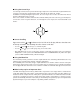
4. DATA COMMUNICATION 4-1. General You can exchange data between your BN Unit and a personal computer using PC sync for Windows. This provides the data communication capabilities illustrated below. • See the manual that comes with PC sync for Windows for details on connecting to a computer and setting up for communication.
4-2. Connecting the CASIO BN Unit to PC Important! Be sure to turn off the power of both your BN Unit and computer before connecting them. Failure to do so can result in damage to the BN Unit, your computer, or the Mini Cradle. 1. Plug the connector at the end of the Mini Cradle´s cable into your computer´s serial port (RS232C). • The serial port is normally labeled COM1, COM2, COM3, or COM4. • If the serial port on your computer does not match the Mini Cradle´s connector, you need to purchase an adaptor.
3. With the side marked CASIO facing up (so you can see it), plug the Mini Cradle connector straight into the BN Unit port. Important! • Make sure you insert the connector as far as it will go, until you hear it snap securely into place. • Do not apply undue force! Doing so can damage the Mini Cradle connector or BN Unit port. To disconnect the Mini Cradle from the CASIO BN Unit 1. Make sure that the power of both the BN Unit and your computer is turned off. 2.
4-3. PC sync for Windows (Brief explanation) If you want to known PC LINK Software for BN-10/20 (PC sync for Windows) in detail, refer to the User´s Guide for this software. This software is similar to FA-127/128 regarding to operation, but have some features which don´t exist with FA-127/128. The following PC, OS for PC and Display for PC are recommended. PC: IBM PC or compatible one OS for PC: Windows 3.
● PROCEDURE The menu items (“Casio” ➝ “Backup” ➝ “Send” or “Receive”) enable you to transfer all the data of your BN Unit fast and efficiency to your PC, e.g. before changing batteries, and - if necessary -back to your BN Unit. While transferring some data between the BN Unit and PC, the following display always appears. “DATA COMMUNICATION IN PROGRESS! TO STOP PRESS [ESC]” 1 To back up the data, choose “Casio”, then “Backup”, and then “Receive” with PC.
5. OPERATION CHECK REMARK: Before entering this check, the reset operation is necessary. Therefore, performing this check, all data saved in the unit will be deleted. Before performing this check, transfer all data saved in BN Unit to a personal computer using PC LINK software package (floppy disk- 2 sheets, a mini cradle and a instruction manual for this software- PC sync for Windows). PC LINK software package is attached to BN Unit and packed together. Refer to 4.
5-2. Operation Check Three items (5. OPTION CHECK/ 6. CRADLE CHECK/ 7. MODEM CHECK) in these nine test items can not be executed for the following reasons. 5. OPTION CHECK- This check can not be performed now, because data transfer between BN Units don't exist and the jack (3 pin) on Main PC board for this data transfer don't exist also. 6. CRADLE CHECK- The special jigs are necessary to perform this check. Check data transfer between BN Unit and PC referring to 4. DATA COMMUNICATION of this manual. 7.
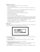
4 PATTERN-3 Press ESC, then 3 button. The following display appears. FRAME SHIFT CAPS ACC COMMAND SEARCH 5 PATTERN-4 Press ESC, then 4 button. The following display appears. ALL DISPLAY SHIFT CAPS ACC COMMAND SEARCH 6 PATTERN-5 Press ESC, then 5 button. The following display appears. NO DISPLAY 7 DD RAM CHECK Press ESC, then 6 button. The following display appears.
8 CONTRAST Press ESC, then 7 button. The following display appears. According to this display, change the contrast value from 00 to 1F using Cursor keys. Doing so, brightness of display changes from dark to light, and then from light to dim. The contrast is best with default contrast value 10. Touch [ESC] Hard lcon Them Test END Touch [<-] Key Then [DRANK] Touch [->] Key Then [THIN] ( [LIGHT] ) << DARK <- + -> Contrast Value : 10 9 PATTERN-6 Press ESC, then 8 button.
2 SRAM MEMORY CHECK Press 1 button, the following display appears. SRAM CHECK (128K)= OK In case of abnormal S-RAM, NG display appears. 3 CHECK SUM Press ESC, then 2 button. The following display appears. ROM SUM (CS8)= XXXX (CS7)= XXXX ROM shown to this display indicates LSI301. 4 BUS CHECK Press ESC, then 3 button. The following display appears.
6 SRAM READ CHECK Press ESC, then 5 button. The following display appears. SRAM CHECK (128K)= OK 7 FLASH CROSS BIT CHECK Press ESC, then 6 button. The following display appears. FLASH CHECK (CS5)= 1M NGF5 (CS4)= 1M NGF4 XXXXXXXX BANKXX “(CS4)= NC” is displayed in stead of “(CS4)= 1M” with BN-10. And “NGF4” is not displayed with BN-10 also. 8 FLASH CROSS BIT CHECK F The flash ROM LSI304 (306) is formatted at first, and then the data for this check are written into LSI304 (306).
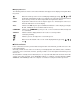
2 AUTO KEY CHECK Pressing 1 button, no display appears. Press 01, 02, ......, then 71 button one after another and in order referring to the illustration described below. Performing this check in wrong order, BEEP sound is emitted for one second. After pressing a key, its key number is displayed. If you want to stop this check halfway, press OK (71) button. Then KEY MENU display described above appears.
3 ALARM1 Pressing 2 button, BEEP sound is emitted twice in one second. Then press ESC button to stop ringing. 4 ALARM2 Pressing 3 button, BEEP sound is emitted three times in one second. Then press ESC button to stop ringing. 5 CLOCK Pressing 4 button, the following display appears. 0:00 0X Then pressing OK button, the following display appears. 12:00 0X Then pressing ESC button, OTHERS MENU display appears. 6 SW CONDITION Pressing 5 button, the following display appears.
8 NMI CHECK The term "NMI" means Non Mask-able Interrupt with CPU. Pressing 7 button, the following display appears. PLEASE NMI Press RESET button on the back of BN Unit using a thin, pointed object. The following display appears. RESET KEY If the AC adapter(AD-A70140) is inserted into the jack, and its output voltage is less than DC 4.4V the following display appears. DET5V Then pressing ESC button, OTHERS MENU display appears. 9 EL ON CHECK (BN-20 only) Pressing 8 button, the blue back light is emitted.
6. ERROR MESSAGES Message Cause Action THAT ALARM TIME IS ALREADY PASSED! The time you are trying to set for an alarm is already passed. This is merely a warning message that appears for about one second. After that, the dialog box closes and the data is stored without the alarm. THAT ALARM TIME IS ALREADY USED! The time you are setting for an alarm is already used. Change the alarm time to one that is not yet used.
Message Cause Action MEMORY IS FULL! You are trying to input data while memory is already full. First try performing the memory management operation to see if more memory can be made available. If this message still appears, it means that memory is really full. Delete data you no longer need to make room for more data. CELLS IN THE RANGE YOU ARE DELETING CONTAIN DATA. DELETE THEM ANYWAY? Some of the cells in a range you are deleting in the SPREADSHEET Mode contain data.
7. TROUBLESHOOTING ■ Power Supply PROBLEM POSSIBLE CAUSES RECOMMENDED ACTIONS Nothing appears on the display when power is turned on. 1.The battery switch on the back of the unit is set to REPLACE BATTERIES. 2.Battery power is low. 3.Display contrast is too light. 1.Slide the battery switch to NORMAL OPERATION. 2.Replace batteries (page 18). 3.Adjust display contrast (page 10). The BN Unit does not operate normally after batteries are replaced. Problem with BN Unit operational settings.
8. LSI PIN FUNCTION 8-1. CPU (LSI1) This CPU is COB (Chip on board). Therefore this CPU cannot be replaced for repair. CPU:UPD3066P (NC3020) Pin No.
8-2. Gate Array (LSI2) Gate array: FM3416 Pin No.
Pin No.
9. CIRCUIT EXPLANATION 9-1. Block Diagram Address bus (BN-20 only) 1 Mbits S-RAM EL driver KEYS (LSI303) DC/AC inverter Buzzer (BN-20 only) 16 Mbits KI/KO EL 34.5 kHz LCD 319 × 160 dots Common- MASK ROM TX/RX CPU Clock (LSI1) (LSI301) TAB(LSI3) 8 Mbits Clock FLASH ROM 10.14 MHz 32.
9-2. Power Supply AC Adapter (7 V) Common mode coil (EF601) Voltage regulator D606 AD-A70140 Q602 IC611 (5 V) D605 V5EXT (5 V) APO:OFF P5 (from CPU) D607 D601 FUSE (F601) V5SYS (5 V) D-D Converter IC603 (3 V→5 V) BLD2 to CPU Q624 Battery (3 V) BLD1 IC601 to CPU Low battery (2.1 V) Voltage regulator Voltage regulator IC605 (3 V) IC606 (2 V) IC602 V2SYS (2 V) V3SYS (3 V) P1 to Gate array Q623 Forced power off Detection of low adapter voltage (4.4 V) (1.
3. When battery voltage becomes to be about 2.1 V, BLD1 terminal voltage becomes to be about 0 V and the low battery message appears even if AC Adapter is used. 4. When battery voltage becomes to be about 1.6 V, BLD2 terminal voltage becomes to be about 0 V and the power is forced to be turned off to prevent the corruption of memory even if AC Adapter is used. 5.
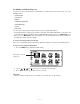
9-3-3. Bias voltage generator IC (IC708) for LCD LCD is driven by steps shaped AC voltage as shown to the right. The number of steps shown to the right is three. This is called 1/3 bias. Generally, if the quantity of pixels in a LCD common line is N dots, the quantity of bias is 1/ N . At this time, contrast of LCD display becomes maximum. The quantity of pixels in a LCD common line is 160 dots. Therefore, the quantity of bias is set to 1/13 by this bias voltage generator circuit. 9-3-4.
10. SCHEMATIC DIAGRAMS Main block (PCB ASSY-A140806)-1/5 X1:Ceramic oscillator for Main system clock (10.14 MHz) X2:Crystal oscillator for Timer clock (32.
Main block (PCB ASSY-A140806)-2/5 FM3416 Gate array — 49 —
Main block (PCB ASSY-A140806)-3/5 ✽ 1 KEY81 (CHECK/TRANS KEY) is a key for TEST, not one for users.
Main block (PCB ASSY-A140806)-4/5 LINE DRIVER/RECEIVER — 51 —
Main block (PCB ASSY-A140806)-5/5 Batteries AC Adapter — 52 —
Memory block (PCB ASSY-A241123) ROM IC320 IC321 R330 LSI308 used not used MASK ROM not used not used FLASH ROM used used not used used Unit's Name BN-10 BN-20 LSI304 LSI306 R335 R336 used not used not used not used used used used not used — 53 — At first FLASH ROM will be used, then MASK ROM will be used.
Display block (LCD ASSY-A140809/A140814)-1/3 Actually, bias for LCD is set to 1/13. BIAS for LCD R718 R717 R716 used not used not used 1/10 1/11 not used not used not used 1/12 used used used 1/13 not used used used 1/14 used not used used 1/15 not used not used used 1/16 used used not used R715 used used not used not used not used not used not used R728 used used used used used used used This circuit (EL and EL driver) is used only with BN-20, is not used with BN-10.
Display block (LCD ASSY-A140809/A140814)-2/3 LCD common terminal driver — 55 —
Display block (LCD PCB ASSY-A140809/A140814)-3/3 LCD segment terminal driver — 56 —
Cradle (A140805) shielded BN-10/20 (PCB-Z456-1) — 57 —
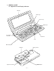
11. DISASSEMBLY * Refer to 13. EXPLODED VIEW (the parts (B and N) are used for only BN-20). 11-1. Disassembly for keyboard side 1. 2. 3. 4. Slide the battery switch g on the back of the BN Unit to the REPLACE BATTERIES position. Remove the battery cover ]. Remove two screws S1 . Remove the lower case [ (+ the cover a) using an opener as shown below. * At this time, take care not to break ribs. Keys Blade of opener 5. 6. 7. 8. 9. 10. 11.
11-2. Disassembly for display side 1. Perform the items 1 ~ 9 and 17 of Disassembly of keyboard side . 2. Remove two screws S5 . 3. Remove the lower case D using a opener as shown bellow. Blade of opener Then remove two axes AX1 of this lower case while opening out as shown below. LCD display Open Lower case (of display side) Axes 4.
12. PARTS LIST N N N N N N N N N N N N N N N N N N N N N N N N N N N N N N Item Code No.
N Item Code No.
N Item Code No.
13.
13. EXPLODED VIEW (2/2) KEY ARRANGEMENT 35 31 ON/OFF 32 33 LIGHT 1 2 3 4 5 6 7 8 9 0 I O P BS ESC Q W E R T Y U TAB A S D F G H J K L SHIFT 1 2 Z X COMMAND C V ACC B N SPACE M , CAPS SYMBOL .
CASIO TECHNO CO.,LTD.