
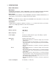
Specifications

— 2 —
CONTENTS
1. SPECIFICATIONS ................................................................................................3
2. GENERAL GUIDE
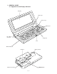
2-1. Appearances and Display Indicators.......................................................5
2-2. Modes and Cursor Keys etc. ....................................................................7
2-3. Backlight Operation (BN-20 only) ..........................................................13
2-4. Power Supply ...........................................................................................14
3. RESET OPERATION and BATTERY REPLACEMENT
3-1. Reset Operation.......................................................................................16
3-2. Battery Replacement ...............................................................................18
4. DATA COMMUNICATION
4-1. General .....................................................................................................24
4-2. Connecting the CASIO BN Unit to PC ...................................................25
4-3. PC sync for Windows (Brief explanation) .............................................27
5. OPERATION CHECK
5-1. To enter the operation check mode .......................................................29
5-2. Operation Check ......................................................................................30
6. ERROR MESSAGES..........................................................................................38
7. TROUBLESHOOTING .......................................................................................40
8. LSI PIN FUNCTION
8-1. CPU ...........................................................................................................41
8-2. Gate Array ................................................................................................42
9. CIRCUIT EXPLANATION
9-1. Block Diagram .........................................................................................44
9-2. Power Supply ...........................................................................................45
9-3. Function ...................................................................................................46
10. SCHEMATIC DIAGRAMS ..................................................................................48
11. DISASSEMBLY
11-1. Disassembly for keyboard side..............................................................58
11-2. Disassembly for display side .................................................................59
12. PARTS LIST .......................................................................................................60
13. EXPLODED VIEW ..............................................................................................63