MIDI Implementation for the CTK-900, WK-3200, and WK-3700 Important! • All mentions of "this Model" in this document refer to the CASIO CTK-900, WK-3200, and WK-3700. Contents Part I MIDI Message Overview 1 Product Configuration as a MIDI Device............................................................................................ 7 1.1 1.2 1.3 1.4 1.5 Controller Block....................................................................................................................................
10.15 10.16 10.17 10.18 10.19 10.20 Vibrato Rate (4CH).............................................................................................................................. 16 Vibrato Depth (4DH)............................................................................................................................ 16 Vibrato Delay (4EH) ............................................................................................................................ 16 Reverb Send (5BH)...............
Part IV This Model's System Exclusive Messages 17 Format............................................................................................................................................ 31 17.1 Message Classifications........................................................................................................................ 31 17.2 Message Structures .............................................................................................................................. 32 17.
Part VI Parameter Set List 26 User Tone Parameter Set .............................................................................................................. 58 27 User Timbre Parameter Set ........................................................................................................... 58 28 User Drum Parameter Set ............................................................................................................. 59 29 User Voice Parameter Set ..................................
40.25 40.26 40.27 40.28 40.29 Algorithm 24 (18H) : Reverse Gate Reverb ........................................................................................ 69 Algorithm 25 (19H) : Reflection .......................................................................................................... 69 Algorithm 26 (1AH) : Flanger ............................................................................................................. 69 Algorithm 27 (1BH) : Reverb ....................................
42.13 42.14 42.15 42.16 42.17 42.18 Part IX Equalizer Mid Frequency Setting Value Table .................................................................................... 77 Equalizer High Frequency Setting Value Table .................................................................................. 77 Equalizer Gain Setting Value Table .................................................................................................... 78 DSP Algorithm ID Table .........................................
Part I MIDI Message Overview 1 Product Configuration as a MIDI Device This Model consists of a controller block and a sound source block as described below. • • Controller Block – Keyboard – Pedals, wheels, and other real-time controllers – Auto accompaniment – Song Memory – SMF Player – Parameter editing tools Sound Source Block – – 1.
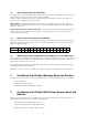
1.3 Sound Source Common Sub-blocks The Sound Source Common Sub-blocks include sound source settings that are not dependent on sound source parts; namely effectors, a mixer, and a drawbar organ waveform synthesizer. Basically, common sub-block parameters can be controlled using System Exclusive messages, but a number of parameters can be controlled using Channel messages.
4 Different Operations Depending on Part Mode Each Part Mode (see 12.1 "About the Part Mode"), which is the sound source operational mode, has different messages for performing operations upon receipt. Each message is explained in the applicable message sections of this document. Part II Channel Message 5 Receive Channel The channel number of Channel messages received by each part is in accordance with each part's receive channel setting, which is configured on this Model.
8 Note On Format Message Format: 9nH kkH vvH n: MIDI Channel Number kk: Key Number vv: Velocity Send Sent when something is played on the keyboard. Receive Received over MIDI Channels that correspond to each part. Any part whose mixer channel is turned off is not received. 9 Polyphonic Key Pressure Format Message Format: AnH kkH vvH n: MIDI Channel Number kk: Key Number vv: Pressure Value Send Operation This message is not sent. Receive Operation This message is not received.
10.1 Bank Select (00H) Format Message Format: BnH 00H vvH (MSB) BnH 20H **H (LSB) n: MIDI Channel Number vv: Value **: Ignored Send Sent when a tone is selected. See the "Tone List" of this Model's User's Guide for details. Receive Receipt causes a change in the tone bank number stored in this Model's memory, but the tone is not actually changed until Program Change is received. For details, see "12 Program Change" in this document, and the "Tone List" in this Model's User's Guide. 10.
10.4 Volume (07H) Format Message Format: BnH 07H vvH n: MIDI Channel Number vv: Value (Note 1) Note 1: The setting value matches the value that is sent and received. Send Sent when the volume of Mixer Part 1 through 16 is changed. Receive Receipt changes the Mixer Part Volume. 10.5 Pan (0AH) Format Message Format: BnH 0AH vvH n: MIDI Channel Number vv: Value (Note 1) Note 1: For information about the relationship between setting values and send/receive values, see "42.
10.
10.9 Sostenuto (42H) Format Message Format: BnH 42H vvH n: MIDI Channel Number vv: Value (Note 1) Note 1: For information about the relationship between setting values and send/receive values, see the "42.1 Off/On Setting Value Table" in "Part VIII Setting Values and Send/Receive Values." Send Sent when the assignable jack is configured for sostenuto and the connected pedal is operated. Receive Receipt performs an operation equivalent to a sostenuto pedal operation. 10.
10.12 Envelope Attack Time (49H) Format Message Format: BnH 49H vvH n: MIDI Channel Number vv: Value (Note 1) Note 1: For information about the relationship between setting values and send/receive values, see "42.5 -64 to 0 to 63 Setting Value Table" in "Part VIII Setting Values and Send/Receive Values". Send Sent when Attack Time is changed with the synthesizer function. Receive Receipt changes Attack Time. 10.
10.15 Vibrato Rate (4CH) Format Message Format: BnH 4CH vvH n: MIDI Channel Number vv: Value (Note 1) Note 1: For information about the relationship between setting values and send/receive values, see "42.5 -64 to 0 to 63 Setting Value Table" in "Part VIII Setting Values and Send/Receive Values". Send Sent when Vibrato Rate is changed with the synthesizer function. Receive Receipt changes Vibrato Rate of Tone Parameter. 10.
10.18 Reverb Send (5BH) Format Message Format: BnH 5BH vvH n: MIDI Channel Number vv: Value (Note 1) Note 1: The setting value matches the value that is sent and received. Send Sent when Reverb Send of Mixer Part 1 through 16 is changed. Receive Receipt changes Reverb Send of Mixer Part 1 through 16. 10.19 Chorus Send (5DH) Format Message Format: BnH 5DH vvH n: MIDI Channel Number vv: Value (Note 1) Note 1: The setting value matches the value that is sent and received.
Send This message is never sent. Receive Receipt changes Filter Cutoff of Tone Parameter. 10.20.2 Filter Resonance Format Message Format: BnH 62H 21H 63H 01H 06H mmH 26H **H n: MIDI Channel Number mm: Value (Note 1) **: Ignored Note 1: For information about the relationship between setting values and send/receive values, see "42.5 -64 to 0 to 63 Setting Value Table" in "Part VIII Setting Values and Send/Receive Values". Send This message is never sent.
Send Sent when Drawbar Organ Parameter is changed on this Model. Receive Receipt changes the drawbar position in accordance with the message contents. 10.20.4 Drawbar Organ Click Format Message Format: BnH 62H 09H 63H 40H 06H mmH 26H **H n: MIDI Channel Number mm: Value (Note 1) **: Ignored Note 1: For information about the relationship between setting values and send/receive values, see the "42.1 Off/On Setting Value Table" in "Part VIII Setting Values and Send/Receive Values.
Send Sent when 3rd Percussion of Drawbar Parameter is changed on this Model. Receive Receipt changes 3rd Percussion the Drawbar Organ Parameter. 10.20.7 Percussion Decay Time Format Message Format: BnH 62H 0CH 63H 40H 06H mmH 26H **H n: MIDI Channel Number mm: Value (Note 1) **: Ignored Note 1: The setting value matches the value that is sent and received. Send Sent when Percussion Decay Time of Drawbar Parameter is changed on this Model. Receive Receipt changes Decay Time of Drawbar Parameter. 10.
10.21.2 Fine Tune Format Message Format: BnH 64H 01H 65H 00H 06H mmH 26H llH n: MIDI Channel Number mm: Value MSB (Note 1) ll: Value LSB (Note 1) Note 1: For information about the relationship between setting values and send/receive values, see "42.7 -99 to 0 to 99 Setting Value Table" in "Part VIII Setting Values and Send/Receive Values". Send Sent when Fine Tune of Mixer Part 1 through 16 is by operation of this Model. Receive Receipt changes Fine Tune of Mixer Part 1 through 16. 10.21.
10.21.5 Null Format Message Format: BnH 64H 7FH 65H 7F n: MIDI Channel Number Send This message is never sent. Receive Receipt deselects RPN. 10.22 All Sound Off (78H) Format Message Format: BnH 78H 00H n: MIDI Channel Number Send This message is never sent. Receive Receipt stops all voices that are sounding. 10.23 Reset All Controllers (79H) Format Message Format: BnH 79H 00H n: MIDI Channel Number Send Sent when the song function is used.
11 Mode Message 11.1 All Notes Off (7BH) Format Message Format: BnH 7BH 00H n: MIDI Channel Number 11.2 Omni Off (7CH) Format Message Format: BnH 7CH 00H n: MIDI Channel Number 11.3 Omni On (7DH) Format Message Format: BnH 7DH 00H n: MIDI Channel Number 11.4 Mono (7EH) Format Message Format: BnH 7EH 00H n: MIDI Channel Number 11.5 Poly (7FH) Format Message Format: BnH 7FH 00H n: MIDI Channel Number Send These messages are never sent.
12 Program Change Format Message Format: CnH ppH n: MIDI Channel Number pp: Program Number Send Sent when a tone is selected. See the "Tone List" of this Model's User's Guide for details about program numbers. Receive Receipt changes the tone of the part corresponding to the MIDI Channel. The selected tone is determined by the program value of this message and the Bank Select message value received prior to this message.
Part III System Message 15 Active Sensing Format Message Format: FEH Send This message is never sent. Receive When this message is received once, the Active Sensing mode is entered. If no MIDI Message is received for a particular amount of time, voices being sounded by this Model's sound source are released, controller is reset, and Active Sensing mode is exited. 16 System Exclusive Message Format Message Format: F0H....
16.1.2 Master Balance Format Message Format: F0H 7FH 7FH 04H 02H llH mmH F7H ll: Value LSB (Note 1) mm: Value MSB (Note 1) Note 1: For information about the relationship between setting values and send/receive values, see "42.6 Pan Setting Value Table" in "Part VIII Setting Values and Send/Receive Values". Send This message is never sent. Receive Receipt changes the Master Pan parameter. Note that the Master Pan parameter cannot be changed with an operation of this Model. 16.1.
16.1.5 Reverb Parameter Format Message Format: F0H 7FH 7FH 04H 05H 01H 01H 01H 01H 01H ppH vvH F7H pp: Parameter vv: Value Type Format Message Format: F0H 7FH 7FH 04H 05H 01H 01H 01H 01H 01H 00H vvH F7H vv: Value (Note 1) Note 1: For information about the relationship between setting values and send/receive values, see "42.10 Reverb Type Setting Value Table" in "Part VIII Setting Values and Send/Receive Values." Send Sent when the Reverb Type parameter of System Reverb is changed.
Note 1: For information about the relationship between setting values and send/receive values, see "42.11 Chorus Type Setting Value Table" in "Part VIII Setting Values and Send/Receive Values." Send Sent when the Chorus Type parameter of System Chorus is changed. Receive Receipt changes the System Chorus Type parameter. Rate Format Message Format: F0H 7FH 7FH 04H 05H 01H 01H 01H 01H 02H 01H vvH F7H vv: Value (Note 1) Note 1: The setting value matches the value that is sent and received.
Send To Reverb Format Message Format: F0H 7FH 7FH 04H 05H 01H 01H 01H 01H 02H 04H vvH F7H vv: Value (Note 1) Note 1: The setting value is the same as the value that is sent. Send This message is never sent. Receive Receipt changes the Chorus Send To Reverb parameter. The Chorus Send to Reverb parameter cannot be changed with an operation of this Model. 16.1.7 GM System Message GM System On Format Message Format: F0H 7EH 7FH 09H 01H F7H Send This message is never sent.
16.1.8 GS Message Message Format: F0H 41H 10H 42H 12H 40H 00H 7FH 00H 41H F7H Send This message is never sent. Receive Receipt performs the same operation as when the GM System On message is received. 16.2 CTK-900/WK-3200/WK-3700 System Exclusive Message Format Message Format: F0H 44H 11H 02H....F7H These messages can control most of the this Model's parameters, as well as user data send/receive with Flash memory and come commands.
Part IV This Model's System Exclusive Messages 17 Format 17.1 Message Classifications This Model's SysEx operations are classified as Parameter type for send and receive of an individual Parameter, and Parameter Set type for Bulk send and receive of a set of parameters. These SysEx types can be further broken down into parameter categories according to the item being transferred.
17.2 Message Structures This Model's System Exclusive Messages is formed of the 13 fields shown below. Whether or not a particular field is included in a message and the length of each field depends on the message. The minimum unit for the length of each field is bytes. If two values are contained within the same byte, they are separated by a slash (/).
aaaB Message Type 00H IPC Individual Parameter Change 01H IPR Individual Parameter Request 02H BDR Oneway Parameter Set Bulk Send 03H BDR Oneway Parameter Set Bulk Request 04H HDS Handshake Parameter Set Bulk Send 05H HDR Handshake Parameter Set Bulk Request 06H Reserved 07H Communication Control for Handshake(EOD,HDA,HDJ,HDE,BSY,EOS,NOP) 17.2.6 6...cat : Category Format: 0000ccccB 0cccccccB = Category (7bit) The category indicates the type of data handled by the System Exclusive Message.
17.2.7 7...prm : Parameter ID Format: 0pppppppB The Parameter ID field indicates the parameter type. When transferring parameters (see "Part V Parameter List" below) individually (as opposed to bulk transfer), this field is used to identify the parameter being transferred by its parameter ID. Any other time, this field is filled with the value 00H. 17.2.8 8...ilen/dlen : index length / data length Format: 0iidddddB This field indicates the size of the "11...index" field and the "12...data" field.
17.2.10 10...index Parameter Index Number When act = 00(IPC) or 01(IPR) Format: 0iiiiiiiB (0jjjjjjjB) (0kkkkkkkB) (0lllllllB) This field contains a supplementary number that points to data when parameters are arrayed. This means that each parameter has a different number, and the length of the number is anywhere from one to four bytes.
ccccB Control Message 0000B 0001B 0010B 0011B 0100B 0101B : 1111B EOD Oneway/Handshake Bulk Dump End of Data (Parameter set transfer complete) HDA Handshake Bulk Dump Acknowledge (Handshake receive successful) HDJ Handshake Bulk Dump Reject (Handshake rejected/stopped) HDE Handshake Bulk Dump Error (Handshake Error) BSY Handshake Bulk Dump Busy (Handshake Busy) EOS Oneway/Handshake Bulk Dump End of Package (Parameter set package complete) 17.2.11 NOP No Operation (No operation) 11...
When act = 02(BDS) or 04(HDS) Format: 0dddddddB 0cccccccB 000000abB For a bulk data transfer operation, the Parameter Set data to be transferred is read sequentially in 16-bit data starting from the top address. Read values are divided into 3-byte segments as shown below, and then sent in sequence. The following is the conversion format, which is the same as the individual parameter 16-bit transfer detailed above.
18 Parameter Operations There are two parameter operations: Individual Parameter Transfer and Individual Parameter Request. A single session is concluded when this Model sends an IPC (Individual Parameter Change) in response to an IPR (Individual Parameter Request) from an external device, or when an IPC is sent by an external device or this Model on its own (not in response to an IPR). Receipt of an IPC by this Model causes the corresponding parameter to be changed.
19.1.2 Session and Subsession Subsession One Parameter Set can be transferred per subsession. Subsession transfers one Parameter Set or data that is broken down into multiple packets for transfer, with EOD (End of data) sent at the end to terminate the send. Data is broken down into multiple packets when a single Parameter Set is larger than a certain size. The Packet Number in the packet's index field is used to indicate the sequential position of a packet relative to the other packets.
19.3 Handshake Protocol Communication Flow A session starts with the receiving device sending a request using an HDR or with the sending device sending HDS data. The sending device does not send the next packet until it receives an ACK from the receiving device. The maximum wait time of at least 2000 msec is reserved. Failure of a response to arrive within the wait time (at least 2000 msec) is treated as a timeout error, and data communication is terminated.
Data Receiver Data Sender HDR → Operation Send Request (Optional) ← HDS Data Send HDA → Acknowledge ← HDS Data Send HDJ → Rejection (Send Canceled) The session can be canceled for any reason by sending an HDJ. The HDJ can be sent by the sending device or the receiving device. The bulk dump session is terminated immediately upon receipt of an HDJ.
Data Receiver Data Sender BDS → Operation Data Send ← BSY Busy (Send Canceled) Data Receiver Data Sender HDR → Operation Send Request ← BSY Busy (Send Canceled) Data Receiver Data Sender HDS → Operation Data Send ← BSY Busy (Send Canceled) The same packet is resent when a checksum mismatch or incompatible data structure error is detected.
Part V Parameter Lists These lists show the parameters that can be transferred individually using System Exclusive Messages. • Note 1: Any parameter that has "r" to the right of its Parameter ID number is a read-only parameter that can be used for obtaining status information only. A parameter with "w" next to its Parameter ID is a write-only parameter, which is used for commands, etc. • Note 2: All values in the System Exclusive Format table are hexadecimal.
System Parameter List ParamID Parameter ps index bit Value Default Setting Value (Decimal) 00r Model Version ID (Note 1) 0000 00 0E 05 0 nn00 = reserved nn01 = CTK-691 nn02 = WK-3000 nn03 = WK-3500 nn04 = reserved nn05 = CTK-900 nn06 = WK-3200 nn07 = WK-3700 n = version (00 to 3F) 03 DSP Bypass (Note 2) 0000 00 10 0-FFFF 0 Bit0...Part1 Bit1....Part2 : Bit15...Part16 0...Nop 1...DSP cancel Note 1: This is the version number of models with the same System Exclusive Model ID = 11-02.
Data Management Command List ParamID Parameter ps index bit Value Default Setting Value (Decimal) 20w Prepare for Data Management (Note 1) 0 00 07 0-127 0 0...
20.3 Command Parameter List System Exclusive Format Field Value 01 SYSEX F0 02 MAN 44 03 MOD 11,02 04 dev Either 00 to 1F, or 7F 05 act 00(IPC), 01(IPR) 06 cat Command = 0 07 prm 00-7F 08 ilen/dlen 0 / bit size - 1 09 ps LSB,MSB = 00,00 10 index Part 11 data See the Parameter List 12 sum None 13 EOX F7 Setup Parameter List ParamID Parameter ps index bit Value Default Setting Value (Decimal) 30 Touch Response 0000 00 02 0-3 1 0...Off 1...Type1 2...
21 Patch Parameter The patch parameter is a temporary area that controls the sound source operation mode. Mixer settings, synthesizer function, DSP function and other editable parameters are also included in these areas. The content of this area is rewritten whenever preset data or user data is selected and manipulated. The parameters in this area are written into the user area whenever data is written into any user data area. 21.
Note 1: See "42.7 -99 to 0 to 99 Setting Value Table". Note 2: See "42.4 -24 to 0 to 24 Setting Value Table". Note 3: See "42.6 Pan Setting Value Table". Note 4: This specifies the volume of data sent from System Chorus to System Reverb. Note 5: When "DSP Bypass" is specified for "DSP Line Bypass," the DSP Line Select settings of all parts are cancelled, and all DSP lines are treated as if they are turned off. This means that notes that are currently sounding are not affected.
System Reverb ParamID Parameter bit Value Default Setting Value (Decimal) 18 Reverb Macro Num (Note 1) 05 00-0F 04 0-15 19 Reverb Level 07 00-7F 40 0-127 1A Reverb Time/Del Feedback 07 00-7F 40 0-127 1B Reverb ER Level 07 00-7F 40 0-127 1C Reverb Hi Damp 07 00-7F 40 0-127 1D Reverb Tone 07 00-7F 7F 0-127 Note 1: Selects the System Reverb preset type. Receipt of GM/GS Reset selects Hall2.
DSP Patch Parameter The values of this parameter do not change when DSP Type and Tone Values are changed. bit Value 2C ParamID Parameter DSP Type Number (Note 1) 08 00-C8 Default Setting Value (Decimal) 0E 0- 99 Preset 100-199 User 200 DSP of Tone 2D DSP Hold 01 0-1 0 0...Off 1...On 2E DSP Level 07 00-7F 64 0-127 2F DSP Pan (Note 2) 07 00-7F 40 -64 to 0 to +63 Note 1: Selects the DSP Type. Receipt of GM/GS Reset selects 014 Delay.
ParamID Parameter bit Value 38 DSP User Parameter0 07 00-7F - 0-127 39 DSP User Parameter1 07 00-7F - 0-127 3A DSP User Parameter2 07 00-7F - 0-127 3B DSP User Parameter3 07 00-7F - 0-127 3C DSP User Parameter4 07 00-7F - 0-127 3D DSP User Parameter5 07 00-7F - 0-127 3E DSP User Parameter6 07 00-7F - 0-127 3F DSP User Parameter7 07 00-7F - 0-127 40 DSP Internal Param00 07 00-7F - 0-127 41 DSP Internal Param01 07 00-7F - 0-127 42 DSP Internal Pa
Basic Parameter List ParamID Parameter bit Value Default Setting Value (Decimal) 50 Tone Number (Note 1) 0E 51 Part Octave Shift 03 2-6 4 -2 to 0 to +2 Oct 52 Part Enable 01 0-1 1 0...Disable (Off) 1...Enable (On) 53 Part Mode (Note 2) 04 0-4 0 0...Normal 1...Rhythm 2...Drawbar 000 000-FFF Note 1: Number of the tone allocated to this part. Note 2: Sets the Normal, Drum and Drawbar Organ modes of the part play operation. For detailed operations, see "12.1 About the Part Mode".
Assignable Controller Parameter ParamID Parameter 70 Modulation Assign 71-73 Reserved 74 Modulation Depth (Note 1) 75-77 Reserved bit Value Default 04 0-9 0 07 00-7F 127 Setting Value (Decimal) Function 0....Off 1....Modulation 2....DSP Parameter0 3....DSP Parameter1 4....DSP Parameter2 5....DSP Parameter3 6....DSP Parameter4 7....DSP Parameter5 8....DSP Parameter6 9....
22 Wave Data Parameters Wave Data Parameters contain address and size information about expanded waveform data. 22.1 Wave Data Information System Exclusive Format Field Value 01 SYSEX F0 02 MAN 44 03 MOD 11,02 04 dev Either 00 to 1F, or 7F 05 act 00(IPC), 01(IPR) 06 cat Wave Data = 08 07 prm 00-7F 08 ilen/dlen 0 / bit size - 1 09 ps LSB,MSB = wave number For details, see "39 About Parameter Set (PS) numbers".
23 Song Data Parameter Song Data Parameters contain address, size, and name information about song sequencer data. 23.1 Song Data Information System Exclusive Format Field Value 01 SYSEX F0 02 MAN 44 03 MOD 11,02 04 dev Either 00 to 1F, or 7F 05 act 00(IPC), 01(IPR) 06 cat Song = 0A 07 prm 00-7F 08 ilen/dlen 0 / bit size - 1 09 ps LSB,MSB = Song number For details, see "39 About Parameter Set (PS) numbers".
24 Rhythm Data Parameters Rhythm Data Parameters contain address, size, and name information about expanded rhythm data. 24.1 Rhythm Data Information System Exclusive Format Field Value 01 SYSEX F0 02 MAN 44 03 MOD 11,02 04 dev Either 00 to 1F, or 7F 05 act 00(IPC), 01(IPR) 06 cat Rhythm = 0B 07 prm 00-7F 08 ilen/dlen 0 / bit size - 1 09 ps LSB,MSB = SMF Data number For details, see "39 About Parameter Set (PS) numbers".
25 SMF Data Parameters SMF Data Parameters contain address, size, and name information about SMF data. 25.1 SMF Data Information System Exclusive Format Field Value 01 SYSEX F0 02 MAN 44 03 MOD 11,02 04 dev Either 00 to 1F, or 7F 05 act 00(IPC), 01(IPR) 06 cat SMF = 10 07 prm 00-7F 08 ilen/dlen 0 / bit size - 1 09 ps LSB,MSB = SMF Data number For details, see "39 About Parameter Set (PS) numbers".
Part VI Parameter Set List This list shows the parameter sets that can be transferred using System Exclusive Message Bulk Dump. 26 User Tone Parameter Set System Exclusive Format Field Value 01 SYSEX F0 02 MAN 44 03 MOD 11,02 04 dev Either 00 to 1F, or 7F 05 act 04(HDS), 05(HDR), 07(Control) 06 cat Tone = 02 07 prm 00-7F 08 ilen/dlen See "IV This Model's System Exclusive Messages". 09 ps Indicates the tone number being transferred.
28 User Drum Parameter Set This is the drum set parameter set. System Exclusive Format Field Value 01 SYSEX F0 02 MAN 44 03 MOD 11,02 04 dev Either 00 to 1F, or 7F 05 act 04(HDS), 05(HDR), 07(Control) 06 cat Drum = 04 07 prm 00-7F 08 ilen/dlen See "IV This Model's System Exclusive Messages". 09 ps Indicates the drum number being transferred. For details, see "39 About Parameter Set (PS) numbers". 10 index See "IV This Model's System Exclusive Messages".
30 User Instrument Parameter Set This is the parameter set that is associated with and sent with Drum. All key numbers are supported, so one drum set is associated with 128 instruments. System Exclusive Format Field Value 01 SYSEX F0 02 MAN 44 03 MOD 11,02 04 dev Either 00 to 1F, or 7F 05 act 04(HDS), 05(HDR), 07(Control) 06 cat Instrument = 06 07 prm 00-7F 08 ilen/dlen See "IV This Model's System Exclusive Messages". 09 ps Indicates this Model's number being transferred.
32 User DSP Parameter Set System Exclusive Format Field Value 01 SYSEX F0 02 MAN 44 03 MOD 11,02 04 dev Either 00 to 1F, or 7F 05 act 04(HDS), 05(HDR), 07(Control) 06 cat DSP = 09 07 prm 00-7F 08 ilen/dlen See "IV This Model's System Exclusive Messages". 09 ps Indicates the DSP number being transferred. For details, see "39 About Parameter Set (PS) numbers" and "DSP Type Number" in "21.1 Patch Common Parameter List". 10 index See "IV This Model's System Exclusive Messages".
34 User Rhythm Pattern System Exclusive Format Field Value 01 SYSEX F0 02 MAN 44 03 MOD 11,02 04 dev Either 00 to 1F, or 7F 05 act 04(HDS), 05(HDR), 07(Control) 06 cat User Rhythm = 0B 07 prm 00 08 ilen/dlen See "IV This Model's System Exclusive Messages". 09 ps Indicates the rhythm number being transferred. For details, see "39 About Parameter Set (PS) numbers". 10 index See "IV This Model's System Exclusive Messages".
Note 1: The relationship between the "Bank", "Number" and "ps (parameter set)" are as shown below.
37 SMF Parameter Set System Exclusive Format Field Value 01 SYSEX F0 02 MAN 44 03 MOD 11,02 04 dev Either 00 to 1F, or 7F 05 act 04(HDS), 05(HDR), 07(Control) 06 cat SMF = 10 07 prm 00-7F 08 ilen/dlen See "IV This Model's System Exclusive Messages". 09 ps Indicates the SMF number being transferred. For details, see "39 About Parameter Set (PS) numbers". 10 index See "IV This Model's System Exclusive Messages". 11 data See "IV This Model's System Exclusive Messages".
38 Flash Memory Image Parameter Set This Parameter Set is used for dumping flash memory contents. One Parameter Set corresponds to an image block of 2 Mbytes of flash memory. The 4 Mbytes of flash memory of this Model is made up of two blocks, so two Parameter Sets are used.
Part VII 40.4 Number DSP Parameter List This list shows the parameters for each of the DSP algorithms. U0 to U7 indicate User Parameters 0 to 7, while I00 to I15 indicate Internal Parameters 00 to 15. Parameters for which no setting range is indicated, receipt of a value from 0 to 127 is assigned as-is to the parameter.
40.7 Number Algorithm 06 (06H) : Compressor Parameter 40.11 Algorithm 10 (0AH) : Phaser Notes Number Parameter Notes U0 Depth - U0 Resonance U1 Attack - U1 Manual - U2 Release - U2 Rate - U3 Level - U3 Depth - I00 Threshold Note 1 U4 Wet Level - Note 1 Note 1:This algorithm adjusts the level at which the compressor effect starts. Note 1:See the "42.5 -64 to 0 to 63 Setting Value Table." 40.8 40.
40.15 Number U0 Algorithm 14 (0EH) : Ring Modulator Parameter OSC Frequency 40.19 Notes Number - U0 Algorithm 18 (12H) : 3-Phase Chorus Parameter Rate1 Notes - U1 LFO Rate - U1 Depth1 - U2 LFO Depth - U2 Rate2 - U3 Wet Level - U3 Depth2 - U4 Dry Level - U4 Wet Level - 40.16 Number U0 Algorithm 15 (0FH) : LoFi Parameter Noise Level 1 40.
40.23 Number Algorithm 22 (16H) : 3-Tap Delay Parameter 40.27 Notes Number Algorithm 26 (1AH) : Flanger Parameter Notes U0 Delay Time - U0 LFO Rate - U1 Wet Level - U1 LFO Depth - U2 Feedback - U2 Feedback Note 1 U3 High Damp - U3 Wet Level - U4 Ratio L - U5 Ratio C - U6 Ratio R - Note 1:See the "42.5 -64 to 0 to 63 Setting Value Table." 40.28 40.
41 DSP Algorithm List (Multi Effect) 41.3 Number The multi-algorithms (M00 to M31) listed below are combinations of the algorithms described above. Parameter operations and other details are the same as the previous algorithms, so there is no separate explanation provided here. 41.
41.6 Number Algorithm M05 (25H) : Multi05 Parameter 41.
41.12 Number Algorithm M11 (2BH) : Multi11 Parameter 41.
41.17 Number 41.
41.23 Number Algorithm M22 (36H) : Multi22 Parameter 41.
41.28 Number Algorithm M27 (3BH) : Multi27 Parameter 41.
Part VIII 42.6 Setting Values and Send/Receive Values 42 Setting Value Table 42.1 Off/On Setting Value Table Value Transmit/Receive Left 00H : : Center 40H : : Right 7FH 42.7 Value Transmit Receive Off 00H 00H-3FH On 7FH 40H-7FH 42.2 Transmit Receive Slow 00H 00H-3FH Fast 7FH 40H-7FH 42.3 -99 to 0 to 99 Setting Value Table Value Transmit/Receive (MSB-LSB) -99 Slow/Fast Setting Value Table Value Pan Setting Value Table : : 0 40H-00H : : 99 7FH-00H 42.
42.10 Reverb Type Setting Value Table Equalizer Low Frequency Setting Value Table Value Transmit/Receive Room1 00H Value Transmit Receive Room2 01H 0(200Hz) 00H 00H-2AH Room3 02H 1(400Hz) 40H 2BH-55H Hall1 03H 2(800Hz) 7FH 56H-7FH Hall2 04H Plate1 05H Delay 06H Panning Delay 07H Plate2 08H Plate3 09H Large Room1 0AH Large Room2 0BH Stadium1 0CH Stadium2 0DH Long Delay 0EH Long Panning Delay 0FH 42.11 42.12 42.
42.15 Equalizer Gain Setting Value Table 42.
Part IX 42.20 MIDI Implementation Notation When a MIDI implementation data value is expressed in binary, the letter "B" (for "binary") is affixed at the end of the value.The following table shows the binary equivalents for some of the values in the most commonly used range (0 to 127). Binary Notation Decimal Hexadecimal Binary Hexadecimal Notation 0 00H 00000000B MIDI implementation sometimes requires that data be expressed in hexadecimal format.
CASIO COMPUTER CO.,LTD.