PX-3/PX-3S MIDI Implementation CASIO COMPUTER CO., LTD. Contents Part I 1 MIDI Message Overview Product Configuration as a MIDI Device.......................................................................................... 6 1.1 1.2 1.3 System Section.................................................................................................................................... 6 Sound Generator Section ...............................................................................................
9.14 9.15 9.16 9.17 9.18 9.19 9.20 9.21 9.22 9.23 9.24 Release Time (48H) .......................................................................................................................... 17 Attack Time (49H).............................................................................................................................. 17 Filter Cut Off (4AH)............................................................................................................................
Part IV Instrument-Specific System Exclusive Messages 16 Format ........................................................................................................................................... 31 16.1 16.2 16.3 Message Classifications .................................................................................................................... 31 Basic Message Structure...................................................................................................................
22 Scale Tune..................................................................................................................................... 44 23 Registration Parameter .................................................................................................................. 44 23.1 23.2 23.3 23.4 Assignable Button 1 Parameter......................................................................................................... 44 Assignable Button 2 Parameter..............................
26.34 26.35 26.36 26.37 26.38 26.39 26.40 26.41 26.42 26.43 Multi17 (Compressor - Phaser) ......................................................................................................... 58 Multi18 (Phaser - Distortion).............................................................................................................. 59 Multi19 (Phaser - Chorus - Auto Pan) ............................................................................................... 59 Multi20 (LFO Wah - Chorus) ......
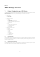
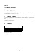
Part I MIDI Message Overview 1 Product Configuration as a MIDI Device As a MIDI device, this Instrument consists of the System Section, Sound Generator Section, and Performance Controller Section described below. Each of these sections sends and receives specific MIDI Messages in accordance with its function.
1.2.1 Sound generator common section The common section consists of sound generator setting blocks that do not depend on the sound generator part, such as system effects, mixer master control, etc. These can be controlled by system exclusive messages that are basically exclusive to this particular Instrument, but several parameters also can be controlled by general universal system exclusive messages. 1.2.
1.2.3 MIDI Receive and Registration The registration (setup) can be switched by MIDI message. For details about messages, see “19.1 Panel Parameter”. When switching the registration by MIDI message, the parts reflected by the zone parameters are determined in accordance with the MIDI send channel setting values of the zone parameters. The following describes an example of how this works.
1.3.3 MIDI Send by Assignable Buttons The message(s) sent when an assignable button is pressed depends on the function assigned to the button. Also, any control change message can be assigned to an assignable button. Since messages that can be sent by an assignable button operation are so diverse and wide-ranging, messages are not covered in detail here. 2 Conditions that Disable Message Send and Receive All MIDI message send and receive is temporarily disabled in all of the following cases.
Part II Channel Message 4 Send Channel For information about the MIDI channels of the channel messages that are sent when this Instrument is played, see “1.2.2 Sound Generator Parts”. Note, however, that the MIDI channel of the performance information that corresponds to the keyboard main part can be changed by zone editing. 5 Receive Channel For information about the MIDI channel numbers of channel messages received by each part, see “1.2.2 Sound Generator Parts”.
7 Note On Format Message Format: 9nH kkH vvH n: MIDI Channel Number kk: Key Number vv: Velocity Send Sent when a key is pressed. Receive Recognized as key press information. 8 Polyphonic Key Pressure Format Message Format: AnH kkH vvH n: MIDI Channel Number kk: Key Number vv: Pressure Value Send This message is not sent by this Instrument. Receive This message is not received by this Instrument.
9.1 Bank Select (00H, 20H) Format Message Format: BnH 00H mmH (MSB) BnH 20H llH (LSB) n: MIDI Channel Number mm: Value ll: Value Send Sent in the following cases. • When a tone selection is made • When a program change message is specified by a zone edit operation For information about numbers, see the Tone List in the User’s Guide. Receive Receipt switches the tone bank number stored in Instrument memory. Note, however, that the tone is not changed until a Program Change message is received.
9.4 Data Entry (06H, 26H) Format Message Format: BnH 06H vvH (MSB) BnH 26H vvH (LSB) n: MIDI Channel Number vv: Value Send Sent when there is a change in the parameters assigned to NRPN and RPN. For details about information assigned to parameters that correspond to NRPN and RPN, see “9.23 NRPN (62H, 63H)” and “9.24 RPN (64H, 65H)”. Receive Receipt changes the parameter assigned to RPN. This Instrument does not have a parameter that corresponds to NRPN. 9.
9.7 Expression (0BH) Format Message Format: BnH 0BH vvH n: MIDI Channel Number vv: Value Send See “1.3.3 MIDI Send by Assignable Buttons”. Receive Receipt changes the part volume level. How this message differs from Volume (07H) Though this message is operationally identical to that of “9.5 Volume (07H),” the purposes of the two messages are different. This message is used, for example, for crescendo/decrescendo, and other forms of expression while playing. “9.
9.9 Hold1 (40H) Format Message Format: BnH 40H vvH n: MIDI Channel Number vv: Value Send Sent in the following cases. • When a pedal that has a sustain (damper) function is operated • Sent when a MIDI channel is specified by a zone edit operation. Receive Receipt performs an operation equivalent to a sustain (damper) pedal operation. Timbre Type Specific Operation This operation differs in accordance with the Timbre Type (see “11.1 About Timber Type”) setting.
9.11 Sostenuto (42H) Format Message Format: BnH 42H vvH n: MIDI Channel Number vv: Value (Note1) Note 1: For information about the relationship between setting values and send/receive values, see the “27.1 Off/On Setting Value Table” in “Part VII Setting Values and Send/Receive Values”. Send Sent in the following cases.
9.13 Filter Resonance (47H) Format Message Format: BnH 47H vvH n: MIDI Channel Number vv: Value (Note1) Note 1: For information about the relationship between setting values and send/receive values, see “27.6 –64 - 0 - +63 Setting Value Table” in “Part VII Setting Values and Send/Receive Values”. Send See “1.3.3 MIDI Send by Assignable Buttons”. Receive Receipt changes the strength of filter resonance. 9.
9.16 Filter Cut Off (4AH) Format Message Format: BnH 4AH vvH n: MIDI Channel Number vv: Value (Note1) Note 1: For information about the relationship between setting values and send/receive values, see “27.6 –64 - 0 - +63 Setting Value Table” in “Part VII Setting Values and Send/Receive Values”. Send Sent when filter is specified by a zone edit operation. Receive Receipt changes how the cut-off filter is applied. 9.
9.19 Vibrato Delay (4EH) Format Message Format: BnH 4EH vvH n: MIDI Channel Number vv: Value (Note1) Note 1: For information about the relationship between setting values and send/receive values, see “27.6 –64 - 0 - +63 Setting Value Table” in “Part VII Setting Values and Send/Receive Values”. Send Sent when the vibrato delay is specified by a zone edit operation. Receive Receipt changes Vib Auto Delay of the LFO Parameter. 9.
9.22 Chorus Send (5DH) Format Message Format: BnH 5DH vvH n: MIDI Channel Number vv: Value Send Sent when the portamento on/off setting is specified by a zone edit operation. Receive Receipt changes the Cho Send Part Parameter. 9.23 NRPN (62H, 63H) Format Message Format: BnH 62H vvH (LSB) BnH 63H vvH (MSB) n: MIDI Channel Number vv: Value Send This message is not sent by this Instrument. Receive This message is not received by this Instrument. 9.23.
9.24.1 Pitch Bend Sensitivity Format Message Format: BnH 64H 00H 65H 00H 06H mmH 26H llH n: MIDI Channel Number mm: Value 0 - 24 ll: Send: 00H, Receive: Ignored Send Sent when the pitch bend range is changed. Receive Receipt changes Pitch Bend Sensitivity. 9.24.2 Fine Tune Format Message Format: BnH 64H 01H 65H 00H 06H mmH 26H llH n: MIDI Channel Number mm: Value MSB ll: Value LSB Send Sent when fine tuning is specified by a zone edit operation. Receive Receipt changes the Fine Tune Part Parameter. 9.
9.24.4 Modulation Depth Format Message Format: BnH 64H 05H 65H 00H 06H mmH 26H 00H n: MIDI Channel Number mm: Value Send This message is not sent by this Instrument. Receive Receipt changes Vib Mod Depth of the LFO Parameter. 9.24.5 Null Format Message Format: BnH 64H 7FH 65H 7F n: MIDI Channel Number Send This message is not sent by this Instrument. Receive Receipt deselects RPN. 10 Mode Messages 10.
10.3 All Notes Off (7BH) Format Message Format: BnH 7BH 00H n: MIDI Channel Number Send Sent when a MIDI channel is specified by a zone edit operation. Receive Receipt of this message releases the currently sounding voice (same as releasing the keyboard key). 10.4 Omni Off (7CH) Format Message Format: BnH 7CH 00H n: MIDI Channel Number Send This message is not sent by this Instrument. Receive Receipt of this message releases the currently sounding voice (same as releasing the keyboard key). 10.
10.7 Poly (7FH) Format Message Format: BnH 7FH 00H n: MIDI Channel Number Send This message is not sent by this Instrument. Receive Receipt of this message stops the currently sounding voice. 11 Program Change Format Message Format: CnH ppH n: MIDI Channel Number pp: Program Number Send Sent in the following cases. • When a tone selection is made • When a program change message is specified by a zone edit operation For information about numbers, see the Tone List in the User’s Guide.
11.2 About DSP 11.2.1 DSP Line Structure and Assignment This Instrument has two DSP lines that can be used simultaneously. Selecting multiple tones with DSP at the same time creates the possibility that there will not be enough DSP lines. If this happens, DSP lines will be assigned in accordance with the DSP line assignment priority specified for each part. When two or more parts have the same priority, the assignment that was made last is given priority.
Part III System Messages 14 Active Sensing Format Message Format: FEH Send This message is not sent by this Instrument. Receive Once this message is received, the Active Sensing mode is entered. If no MIDI message is received for a specified amount of time, voices being sounded by this Instrument’s sound source are released, the controller is reset, and the Active Sensing mode is exited. 15 System Exclusive Message Format Message Format: F0H....
15.1.2 Master Balance Format Message Format: F0H 7FH 7FH 04H 02H llH mmH F7H ll: Value LSB (Note1) mm: Value MSB (Note1) Note 1: For information about the relationship between setting values and send/receive values, see “27.8 Pan Setting Value Table” in “Part VII Setting Values and Send/Receive Values”. Send This message is not sent by this Instrument. Receive Receipt changes the Master Pan parameter. Note that the Master Pan parameter cannot be changed with an Instrument operation. 15.1.
15.1.5 Reverb Parameter Format Message Format: F0H 7FH 7FH 04H 05H 01H 01H 01H 01H 01H ppH vvH F7H pp: Parameter vv: Value Type Format Message Format: F0H 7FH 7FH 04H 05H 01H 01H 01H 01H 01H 00H vvH F7H vv: Value (Note1) Note 1: For information about the relationship between setting values and send/receive values, see “27.9 Reverb Type Setting Value Table” in “Part VII Setting Values and Send/Receive Values”. Send This message is sent when the System Reverb Type setting is changed.
Send This message is sent when the System Chorus Type setting is changed. Receive Receipt changes the System Chorus Type parameter. Rate Format Message Format: F0H 7FH 7FH 04H 05H 01H 01H 01H 01H 02H 01H vvH F7H vv: Value Send This message is not sent by this Instrument. Receive Receipt changes the System Chorus Rate parameter. Depth Format Message Format: F0H 7FH 7FH 04H 05H 01H 01H 01H 01H 02H 02H vvH F7H vv: Value Send This message is not sent by this Instrument.
15.1.7 GM System Message GM System On Format 1 Message Format: F0H 7EH 7FH 09H 01H F7H Send This message is not sent by this Instrument. Receive Receipt puts the sound source into a GM sound source mode. Also, the Scale Tune Enable setting shown under “20.7 Part Parameters” for parts C01 through C16 become zero, which disables the temperament (scale) function. GM System Off Format Message Format: F0H 7EH 7FH 09H 02H F7H Send This message is not sent by this Instrument.
Part IV Instrument-Specific System Exclusive Messages 16 Format This section explains the format of the Instrument-specific System Exclusive Messages. See “Part V Parameter List” for information about what type of data can actually be sent. 16.1 Message Classifications Basically, the operation that corresponds to Instrument-specific system exclusive messages is parameter data transfer. The following operations can be performed from an external device using this parameter transfer message.
16.3 Field Formats 16.3.1 SX : System Exclusive Message Status Format: 11110000B (F0H) This is the System Exclusive Message status byte established by the MIDI standard. 16.3.2 MAN : Manufacturer’s ID Format: 01000100B (CASIO = 44H) Indicates this Instrument’s manufacturer ID. 16.3.3 MOD : Model ID Format: MSB 00010101B (15H) LSB 00000010B (02H) These two successive bytes (MSB, LSB) indicate the PX-130/135/330/3/3S/730/735/7/830, AP-220/420/620/6 model ID. 16.3.
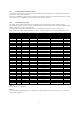
16.3.6 cat : Category Format: 0cccccccB 0cccccccB = Category (7bit) The category indicates the categories of data handled by the System Exclusive Message. The ID number (ID) of the category is indicated on the left, while the communication operation (Action) is indicated on the right. Category Transfer ID (c) Parameter Set 00H System Individual Parameter A 01H Setup A 02H Patch A 03H Tone A 12H Scale Tune A 14H Registration A 15H Registration Bank A A ..
Block Bit Field Division • Case 1 When an array has three or fewer nesting levels and the number of arrays in each dimension is 128 or less, they are assigned below the three 7-bit fields. Unused regions are filled with zeros. Example: parameter [A][B][C] With a 3-dimensional array parameter that consists of A=8 (3 bits), B=5 (3 bits) and C=10 (4 bits), the block bit fields are allocated as: Block = 0000aaa 000bbb ccccccc (Binary).
16.3.13 data : Parameter Data Format: index0 0dddddddB (0eeeeeeeB) (0fffffffB) (0gggggggB) (0hhhhhhhB) index1 0dddddddB (0eeeeeeeB) (0fffffffB) (0gggggggB) (0hhhhhhhB) index2 0dddddddB (0eeeeeeeB) (0fffffffB) (0gggggggB) (0hhhhhhhB) : : indexN 0dddddddB (0eeeeeeeB) (0fffffffB) (0gggggggB) (0hhhhhhhB) Parameter data indicates the parameter value. The data array is a list of len + 1 data items. For a one data item structure, the length depends on the data bit width, as shown below.
17 Parameter Transfer There are two parameter operations: Individual Parameter Transfer and Individual Parameter Request. A single session is concluded only when this Instrument returns an IPS (Individual Parameter Send) in response to an IPR (Individual Parameter Request) from an external device, or when an external device or this Instrument spontaneously sends an IPS. If this Instrument received an IPS, the value of the applicable parameter is changed.
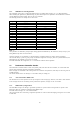
Part V Parameter List How to Read the Tables Number Base Notation “Size” indicates the parameter value bit width as a decimal value. The bit field position of “Block” as a decimal value. Values used in the explanations under “Description” are all decimal values, unless specified otherwise. Values other than those described above are all hexadecimal. R/W field The R/W field indicates whether an IPR (Individual Parameter Request) read operation or IPS (Individual Parameter Send) write operation is enabled.
19 Setup Parameter Setup Parameters put a device into the setup mode. 19.1 Panel Parameter Parameter Registration Number For Midi ID R/W Block 0024 R/W 000000 Size Array 8 Min-Def-Max Description 01 00-00-FF 0...Bank1 Registration1 1...Bank1 Registration2 : 8...Bank2 Registration1 9...Bank2 Registration2 : 63...Bank8 Registration8 (Note1) Note 1: Operation is not guaranteed for values of 64 (40H) or greater. 19.
20.3 System Chorus Parameter Parameter ID R/W Block Cancel 0050 R/W 000000 Type Rate Depth Feedback Tone 0051 0052 0053 0054 0055 R/W R/W R/W R/W R/W Size Array Min-Def-Max Description 1 01 00-00-01 7 7 7 7 7 01 01 01 01 01 00-02-0F 00-0B-7F 00-21-7F 00-00-7F 00-4B-7F 0...Normal 1...Cancel 1-16 (Note1) 0-127 0-127 0-127 0-127 Note 1: Selects the System Chorus preset type. Receipt of GM/GS Reset selects Chorus3.
20.
20.8 Part Registration Parameter Parameters that have the same names as Part Parameters have the same functions as well.
21 Tone Parameters 21.1 Basic Parameters Parameter ID R/W Block Size Array Name Timbre Type 0000 0001 R/W R/W 000000 7 4 10 01 Timbre Num Oct Shift Line Select 0002 0003 0004 R/W R/W R/W 14 3 1 01 01 01 Level Touch Sens Sys Fx Send Override 0005 0006 0007 R/W R/W R/W 7 7 1 01 01 01 Cho Normal Send Rev Send Acou Reso Send 0008 000A 000B R/W R/W R/W 7 7 7 01 01 01 Min-Def-Max Description Ascii Character 0...Melody 1...Piano 2...Drum 3...reserved 4...
21.
22 Scale Tune Parameter ID R/W Block Size Array Min-Def-Max Note 0000 R/W 000000 8 0C 00-80-FF A Key Mode 0001 R/W 1 01 00-00-01 23 Description –128 - 0 - 127 Array : Note 0....C 1....C# 2....D 3....D# 4....E 5....F 6....F# 7....G 8....G# 9....A 10...A# 11...B 0...Relative 1...Absolute Registration Parameter Registration parameters are this Instrument’s registration setting data. 23.
23.
23.4 Equalizer Parameter This is a registration parameter whose operation is basically the same as the Master Equalizer Parameter.
Part VI DSP Parameter List 25 DSP Algorithm ID Tables The lists in this section show the DSP algorithms that are built into this Instrument. 25.
26 DSP Parameter Set Types This section describes the DSP parameter combination patterns of each algorithm specified in the “Parameter Set Type” column of “25 DSP Algorithm ID Tables”. Note: The characteristics of a DSP are different depending on the tone, even if the same algorithm is used. Because of this, the same algorithm may not produce the same effect for different tones. 26.
26.5 Chorus Parameter Number Parameter7[00] Parameter Name Value Rate 00 - 7F Notes Parameter7[01] Depth 00 - 7F Parameter7[02] Feedback 00 - 7F Parameter7[03] Wet Level 00 - 7F Parameter7[04] Polarity 00 - 7F Note2 Value Notes Note1 Note 1: See “27.6 –64 - 0 +63 Setting Value Table”. Note 2: See “27.2 –/+ Setting Value Table”. 26.6 Tremolo Parameter Number Parameter Name Parameter7[00] Rate 00 - 7F Parameter7[01] Depth 00 - 7F 26.
26.9 Drive Rotary Parameter Number Parameter Name Value Parameter7[00] Overdrive Gain 00 - 7F Notes Parameter7[01] Overdrive Level 00 - 7F Parameter7[02] Speed 00 - 7F Note1 Parameter7[03] Brake 00 - 7F Note2 Parameter7[04] Fall Accel 00 - 7F Parameter7[05] Rise Accel 00 - 7F Parameter7[06] Slow Rate 00 - 7F Parameter7[07] Fast Rate 00 - 7F Note 1: See “27.3 Slow/Fast Setting Value Table”. Note 2: See “27.4 Rotate/Brake Setting Value Table”. 26.
26.13 Phaser Parameter Number Parameter7[00] Parameter Name Value Resonance 00 - 7F Parameter7[01] Manual 00 - 7F Parameter7[02] Rate 00 - 7F Parameter7[03] Depth 00 - 7F Parameter7[04] Wet Level 00 - 7F Notes Note1 Note 1: See “27.6 –64 - 0 +63 Setting Value Table”. 26.
26.18 Multi01 (Enhancer - Chorus) Parameter Number Parameter7[00] Parameter Name Value EnLowFreq 00 - 7F Parameter7[01] EnLowGain 00 - 7F Parameter7[02] En HiFreq 00 - 7F Parameter7[03] En HiGain 00 - 7F Parameter7[04] Cho Rate 00 - 7F Parameter7[05] Cho Depth 00 - 7F Parameter7[06] Chorus FB 00 - 7F Parameter7[07] ChoWetLvl 00 - 7F Notes Note1 Note 1: See “27.6 –64 - 0 +63 Setting Value Table”. 26.
26.21 Multi04 (Compressor - Chorus) Parameter Number Parameter7[00] Parameter Name Value Cmp Depth 00 - 7F Parameter7[01] CmpAttack 00 - 7F Parameter7[02] Cmp Reles 00 - 7F Parameter7[03] Cmp Level 00 - 7F Parameter7[04] Cho Rate 00 - 7F Notes Parameter7[05] Cho Depth 00 - 7F Parameter7[06] Chorus FB 00 - 7F Parameter7[07] ChoWetLvl 00 - 7F Parameter7[08] Cho Polari 00 - 7F Note2 Value Notes Note1 Note 1: See “27.6 –64 - 0 +63 Setting Value Table”. Note 2: See “27.
26.23 Multi06 (Phaser - Auto Pan) Parameter Number Parameter7[00] Parameter Name Value Pha Reso 00 - 7F Parameter7[01] PhaManual 00 - 7F Parameter7[02] Pha Rate 00 - 7F Parameter7[03] Pha Depth 00 - 7F Parameter7[04] PhaWetLvl 00 - 7F Notes Note1 Parameter7[05] APan Rate 00 - 7F Parameter7[06] APanDepth 00 - 7F Parameter7[07] Pha Skip 00 - 7F Note2 Parameter Name Value Notes Cho Rate 00 - 7F Note 1: See “27.6 –64 - 0 +63 Setting Value Table”. Note 2: See “27.
26.25 Multi08 (Auto Wah - Phaser) Parameter Number Parameter7[00] Parameter Name Value AWh Input 00 - 7F Parameter7[01] AWh Reso 00 - 7F Parameter7[02] AWhManual 00 - 7F Parameter7[03] AWh Depth 00 - 7F Parameter7[04] Pha Reso 00 - 7F Notes Note1 Parameter7[05] PhaManual 00 - 7F Parameter7[06] Pha Rate 00 - 7F Note1 Parameter7[07] Pha Depth 00 - 7F Parameter7[08] PhaWetLvl 00 - 7F Parameter7[09] AWh Skip 00 - 7F Note2 Notes Note 1: See “27.
26.27 Multi10 (Distortion - Chorus) Parameter Number Parameter7[00] Parameter Name Value Dist Gain 00 - 7F Parameter7[01] Dist Low 00 - 7F Parameter7[02] Dist High 00 - 7F Parameter7[03] DistLevel 00 - 7F Parameter7[04] Cho Rate 00 - 7F Notes Parameter7[05] Cho Depth 00 - 7F Parameter7[06] Chorus FB 00 - 7F Parameter7[07] ChoWetLvl 00 - 7F Parameter7[08] Cho Polari 00 - 7F Note2 Parameter7[09] Dist Skip 00 - 7F Note3 Note1 Note 1: See “27.
26.
26.32 Multi15 (Compressor - Auto Pan) Parameter Number Parameter7[00] Parameter Name Value Cmp Depth 00 - 7F Notes Parameter7[01] CmpAttack 00 - 7F Parameter7[02] Cmp Reles 00 - 7F Parameter7[03] Cmp Level 00 - 7F Parameter7[04] APan Rate 00 - 7F Parameter7[05] APanDepth 00 - 7F Parameter7[06] APan Skip 00 - 7F Note1 Parameter Name Value Notes Cmp Depth 00 - 7F Note 1: See “27.1 Off/On Setting Value Table”. 26.
26.35 Multi18 (Phaser - Distortion) Parameter Number Parameter7[00] Parameter Name Value Pha Reso 00 - 7F Parameter7[01] PhaManual 00 - 7F Parameter7[02] Pha Rate 00 - 7F Parameter7[03] Pha Depth 00 - 7F Parameter7[04] PhaWetLvl 00 - 7F Parameter7[05] Dist Gain 00 - 7F Parameter7[06] Dist Low 00 - 7F Parameter7[07] Dist High 00 - 7F Parameter7[08] DistLevel 00 - 7F Parameter7[09] Pha Skip 00 - 7F Notes Note1 Note2 Note 1: See “27.6 –64 - 0 +63 Setting Value Table”.
26.37 Multi20 (LFO Wah - Chorus) Parameter Number Parameter7[00] Parameter Name Value LWh Input 00 - 7F Parameter7[01] LWh Reso 00 - 7F Parameter7[02] LWhManual 00 - 7F Parameter7[03] LWh Rate 00 - 7F Parameter7[04] LWh Depth 00 - 7F Notes Parameter7[05] Cho Rate 00 - 7F Parameter7[06] Cho Depth 00 - 7F Parameter7[07] Chorus FB 00 - 7F Parameter7[08] ChoWetLvl 00 - 7F Parameter7[09] ChoPolari 00 - 7F Note2 Notes Note1 Note 1: See “27.6 –64 - 0 +63 Setting Value Table”.
26.
26.
26.
Part VII 27.6 Setting Values and Send/ Receive Values 27 27.1 –64 - 0 - +63 Setting Value Table Transmit/Receive Value Parameter 00H –64 01H –63 : : 40H 0 : : 7EH +62 7FH +63 Setting Value Tables Off/On Setting Value Table 27.7 –100 - 0 - +99 Setting Value Table Transmit Value Receive Value Parameter 00H 00H - 3FH Off Transmit/Receive Value 7FH 40H - 7FH On (MSB-LSB) 27.
27.9 Reverb Type Setting Value Table Transmit / Receive Value Parameter 00H Room1 01H Room2 02H Room3 - 03H Hall1 Large Hall 04H Hall2 Hall 05H Plate1 - 06H Delay - 07H Panning Delay - 08H Plate2 - 09H Plate3 - 0AH Large Room1 - 0BH Large Room2 - 0CH Stadium1 Stadium 0DH Stadium2 - 0EH Long Delay - 0FH Long Panning Delay - 27.10 27.
27.14 Equalizer Gain Setting Value Table 27.
Part VIII 28.2 MIDI Implementation Notation When a MIDI implementation data value is expressed in binary, the letter “B” (for “binary”) is affixed at the end of the value. The table below shows the binary equivalents for the decimal values 0 through 127, which are often used for settings. 28 28.1 Value Notation Hexadecimal Notation MIDI implementation sometimes requires that data be expressed in hexadecimal format. Hexadecimal values are indicated by the letter “H” after the value.
MA1201-B