(without price) QV-2900UX (KX-787) JUL.
CONTENTS SPECIFICATIONS ....................................................................................................................................... 1 BLOCK DIAGRAM ...................................................................................................................................... 3 ADJUSTMENT ............................................................................................................................................ 4 ■ Preparation ...............................
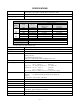
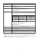
SPECIFICATIONS File Format Still images (including panoramas): JPEG (Exif. Ver. 2.
Viewfinder LCD Monitor or optical viewfinder Clock Built-in quartz digital timepiece for time and date recording and storage with image data; auto calendar up to 2049 Input/Output Terminals DIGITAL IN/OUT, USB port (special mini port), AC adaptor connector, VIDEO OUT (NTSC, PAL), External flash sync terminal Power Supply Four AA-size alkaline or lithium batteries Four AA-size nickel-metal hydride rechargeable batteries (NP-H3) AC adaptor (AD-C620) AC adaptor charger (BC-3HA) Battery Life The values
BLOCK DIAGRAM R G LED KB-PCB FLASH,MACRO,TIMER, LED,SHIFT 6pin C-FPC C-PCB AD9803 3.3V ICX284AQ 22pin CDSSEN CDSSCK CDSSDATA TGSEN TGSCK TGSDATA TGCLK1 TGCLK2 PBLK RESETB CDS+AGC+ADC CCD (2Mpix) CXD2470R 36.0MHz TG 3.3V 5.0V 15.0V -7.5V 15.0V -7.5V 80pin D0 D1 D2 D3 D4 D5 D6 D7 D8 D9 CSUBN HD VD VCC15 x 2 VEE7.5 x 2 VCC3 x 5 CGND x 8 3.3V 3.3V FLASH/MASK ROM (16Mbit) SDRAM(64Mbit) Detection SW 3.3V ADR BUFFER 3.3V CF 3.3V 3.
ADJUSTMENT ■ Preparation 1. PC (IBM Compatible)/OS:Windows 95/98 2. Link cable. 3. Adjustment program 1) adj715.exe (Color adjustment data transfer program) 2) fload.exe (Data transfer program for PC) 3) _romxxxx.bin (Program data) 4) _gmenuxxxx.bin (Graphic menu data) Notes: XXXX is 4-digit number depending upon the program version. 4. AC adaptor or stabilizer 5. Digital oscilloscope 6. Multimeter 7. Ammeter 8. Frequency counter 9. TV (with video terminal) 10. Video cable 11.
1. PROGRAM LOADING 1-1. Important notice Flash ROM on the D-PCB contains camera’s operating program and graphic menu. The D-PCB is used in the models QV-2400UX and QV-2900UX, however, the programs are different. Therefore, the PCB provided as a spare part cannot be discriminated which program is recorded. (Or old program may be recorded.) Be sure to load the program after you replace the D-PCB.
7. Connect an AC adaptor and turn the camera on within 5 seconds. Camera may be turned on automatically when an AC adaptor is connected. If not, use the power switch. Display shows “read time out” on Status screen and program data cannot be loaded if it takes too long between clicking Progress button and turning camera on. 8. Program data is transferred. Program executes Transfer, Erase, Program in order. 9. 10. 11. 12. 13. Program is loaded properly if Status screen shows “program completed”.
2. Program version upgrading Please check the version and update it if the version is not updated. Note: Be sure to use AC adaptor. 2-1. How to confirm the program (graphic menu) version 1. 2. Boot the test mode. Turn the power on while pushing SHIFT and MENU keys. Check the LCD display. (Example) TEST MODE PROG 01. 04. 23. 16. 13 r Program version GMENU 01. 04. 06. 10. 39 r Graphic menu version ···· (Latest version as of May 30, 2001.
2-2. Upgrading using CF card 1. Copy the latest upgraded program (_romXXXX.bin) and graphic menu (_gmenuXXXX.bin) on CF card’s root directory and set the CF card in the camera. 2. Connect an AC adaptor to the camera. 3. Set the camera in PLAY mode and turn the power on while pushing MENU key. The following screen will be shown. 4. Press [ + ] key to select “YES” and push the shutter button. The following screen will be shown and loading starts. 5.
3. Test mode Note: Do not perform the menu item unless explained here. (It may damage the internal data and camera becomes unusable.) 3-1. Booting To boot the test mode; Turn the camera on while pressing SHIFT and MENU buttons. To boot MENU1 (Must be done in the test mode) Press SHIFT ➜ SHIFT ➜ MENU keys in order rapidly. To boot MENU2 (Must be done in the test mode) Press FLASH ➜ FLASH ➜ MENU keys in order rapidly.
3 MENU2 4 MENU3 — 10 —
4. Adjustment 4-1. Flash adjustment 1. General When you exchange a flash unit or lens unit please perform this adjustment. 2. Necessary equipment (1) Dark room (2) AC adaptor (3) Gray paper (Superior's oxford gray No. 22) The following sizes are available from us (also available from camra shop). Parts code 1904 5411 1904 5412 Parts name Superior photographing background paper Sperior photographing background paper Specifications No. 22 (1.75 x 2.7 m) No. 22 (2.72 x 11 m) 3.
4-2. Flash operation and recharge operation 1. General When you exchange a flash unit, please perform this adjustment. 2. Necessary equipment (1) Dark room (2) AC adaptor (3) Gray paper (Superior's oxford gray No. 22) The following sizes are available from us (also available from camra shop). Parts code 1904 5411 1904 5412 Parts name Superior photographing background paper Sperior photographing background paper Specifications No. 22 (1.75 x 2.7m) No. 22 (2.72 x 11m) 3.
4-3. Current consumption 1. General When consumption of a battery is early, check. 2. Conditions • Set QV-2900UX to “PLAY” mode. 3. Preparation (1) Voltage regulator. (2) Ammeter. 4. Adjustment procedure (1) Current consumption (DC in = 6.0 ± 0.1 [V]) • Make sure that current consumption is less than 500 mA in PLAY mode. • Make sure that current consumption is less than 650 mA in REC mode.
4-4. VCOM DC adjustment 1. General Perform these adjustments when you replace LCD module or D-PCB. 2. Preparation (1) (2) (3) (3) AC adaptor or stabilizer. Photo sensor (S1153)/ Photo sensor amp (C2719) Digital oscilloscope or AC meter. B. P. F NTSC: Center frequency; approx. 60 ± 5 Hz PAL: Center frequency; approx. 50 ± 5 Hz 3. Adjustment and checking (1) Boot MENU 1 on the test mode. 1. Turn the camera on while pushing SHIFT and MENU keys. 2. Push SHIFT keys twice then MENU keys rapidly.
Note: Easy adjustment (1) Boot MENU 1 on the test mode. 1. Turn the camera on while pushing SHIFT and MENU keys. 2. Push SHIFT keys twice then MENU keys rapidly. (2) Select and execute GRAY SCALE (10 STEP). (3) Adjust VR321 for distinctive 10 gray steps.
4-5. Operation check 1. General After repairs, please check if needed. 2. Preparation (1) Batteries. (2) AC adaptor. (3) PC (IBM compatible)/OS:Windows 95/98. (4) Link cable. (5) Photo loader (program). (6) TV (with video teminal). (7) Video cable. (8) USB cable/USB driver (9) Test chart (for photography check) (That which carried out color printing of picture data "CHART1.JPG" and the "CHART2.JPG".) 3. Check matter (1) Shock and flash check (essential) 1 Shoot the test chart without flashing.
5. D-PCB Assy 5-1. VCO free run frequency adjustment Room temperature should be 20 ± 10 °C 1. Preparation • AC adaptor or voltage regulator • Frequency counter 2. Adjustment procedure (1) Connect SYF (CP355) and GND (CP344). (2) Monitor HDB (CP301) with frequency counter and adjust VR320 so that frequency becomes 15.734 ± 0.1 KHz. (3) After completing adjustment, disconnect SYF (CP355) and GND (CP344). 5-2. VCOM AC adjustment and VCOM DC coarse adjustment 1.
5-3. RGB AMP and Sub-Brightness voltage setting adjustment 1. General Perform the following adjustments in order. 5-3. RGB AMP and Sub-Brightness voltage setting adjustment 5-4. Contrast and Brightness voltage setting adjustment 5-5. TINT setting adjustment 2. Preparation • AC adaptor or voltage regulator • Digital oscilloscope 3. Adjustment procedure (1) Start up Test mode Menu1. 1. Turn POWER on while pressing SHIFT key and MENU button simultaneously 2.
5-4. Contrast and Brightness voltage setting adjustment 1. Preparation • AC adaptor or voltage regulator • Digital oscilloscope 2. Adjustment procedure (1) Start up Test mode Menu1. 1. Turn POWER on while pressing SHIFT key and MENU button simultaneously 2. Quickly press keys in the order of SHIFT key, SHIFT key and MENU key. (2) Select / Execute GRAY SCALE (10 step). (NTSC) (3) Trigger VG waveform (CP322) by FRP (CP300) signal to adjust as noted below.
5-5. TINT setting adjustment 1. Preparation • AC adaptor or voltage regulator • Digital oscilloscope 2. Adjustment procedure (1) Start up Test mode Menu1. 1. Turn POWER on while pressing SHIFT key and MENU button simultaneously 2. Quickly press keys in the order of SHIFT key, SHIFT key and MENU key. (2) Select / Execute COLOR BAR. (NTSC) (3) Trigger FRP (CP300) signal to adjust as noted below.
6. PW-PCB Assy 6-1. VCC3, VCC3-MD, VCC5, VCC7.5, EVCC3 Voltage check 1. Preparation • AC adaptor or voltage regulator • Multimeter 2. Adjustment procedure Confirm the following voltages. VCC3 (CP110) = 3.30 ± 0.10 [V] VCC3 -MD (CP115) = 3.30 ± 0.10 [V] VCC5 (CP125) = 5.00 ± 0.15 [V] VCC7.5 (CP130) = 7.50 ± 0.50 [V] EVCC3 (CP140) = 3.30 ± 0.10 [V] 6-2. VCC15, VEE7.5 Adjustment 1. Preparation • AC adaptor or voltage regulator • Multimeter 2. Adjustment procedure • Adjust VR135 so that VCC15 (CP136) = 15.
DISASSEMBLY Tool 3. Remove the screw at the bottom. Soldering iron / solder / desoldering wire precision screwdrivers / Tweezers Discharge tool (Resistor 1.5 kΩ 5 W) 4. Remove the screw at the bottom. Main block 1. Remove CF card. 5. Remove the screw on the side of the lens. 2. Remove the battery. 6. Remove the screw on the side of the lens.
7. Pull to the right with pushing the arrowed area. 11. Open the case. 8. Remove the front case block. 12. Remove the connector (CN530). 9. Rotate the lens and remove the screw on the side. 13. Remove the connector (CN522). 10. Rotate the lens and remove the screw on the side. 14. Remove the connector (CN521).
15. Remove the connector (CN900). 19. Remove the screw affixing the lens block. 16. Remove the connector (CN101). 20. Remove the screw affixing the lens block. 17. Lift up the bending of solderless terminal. 21. Remove the connector (CN510). 18. Remove the silver screw. 22. Separated in three blocks.
Lower case block 1. Remove the screw. 5. Remove the battery cover. 2. The screw (1.7 × 9 black) 6. Remove the screw at the bottom. 3. Remove the JK-PCB. 7. Open the case. 4. Remove the connector (CN800). 8. Remove the upper panel.
9. Remove the connector (CN100). 13. Remove the screw. 10. Remove the battery holder. 14. Remove the screw. 11. Remove the screw. 15. Remove the PW-PCB. 12. Remove the KA-PCB.
Upper case block 1. Remove the screw. 5. Remove the screw. 2. Remove the D-PCB. 6. Remove the screw. 3. Remove the connector (CN540). 7. Remove the screw. 4. Remove the connector (CN340). 8. Remove the Back-light.
9. Remove the LCD. 10. Remove the screw. 11. Remove the screw. 12. Remove the KB-PCB.
Lens block 1. Remove the screw. 5. Discharge flash capacitor. (locates between CP400 and CP401) magnified picture 2. Remove the screw. 3. Remove the case. 6. Unsolder the 8 lead wire. 4. Peel off the insulation sheet.
7. Remove the screw. (1.7×12 silver) 10. Remove the flash block. ✽ tips for the assembly 11. Unsolder the purple lead wire. Tighten the screw as hard as there is a space. 12. Remove the ST-PCB. 8. Remove the screw. 13. Remove the connector (CN251). 9. Remove the connector (CN400).
14. Remove the connector (CN250). 18. Unsolder two lead wires. black orange 15 Remove the connector (CN290). 19. Remove the connector (CN750). 16. Remove the screw. 20. Remove the connector (CN700). 17. Remove the C-PCB. 21. Remove the screw.
22. Remove the MD-PCB. 23. Rotate L-case unit and remove the screw . 24. Remove the screw. 25. Remove the L-case unit.
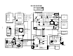
EXPLODED VIEW 28 5 6 30 58 38 34 S11 S12 40 S9 29 35 45 S1 S7 × 2 23 S6 S4 11 37 8 17 49 22 S4 9 57 12 S11 ×2 32 20 S9 15 S6 S6 S1 × 2 S10 50 S6 7 1 10 36 S3 56 S6 × 2 55 S10 S2 16 21 33 S5 19 S8 S3 × 2 53 51 52 24 44 26 4 14 S4 × 2 25 43 27 S8 S11 42 54 S5 13 39 2 47 31 3 18 41 48 S7 46 — 33 —
PARTS PRICE LIST MAIN BODY COMPONENT N Item Code No.
N Item 51 52 53 54 55 56 57 58 S1 S2 S3 S4 S5 S6 S7 S8 S9 S10 S11 S12 Code No. 1000 1733 1003 4797 1004 0278 1002 8728 1003 4926 1003 8341 1003 8349 6614 3450 1003 6886 1002 8722 1002 8704 1001 2551 1002 8705 1001 2596 1002 8702 5861 3551 1003 4921 1002 8693 1002 5765 5860 5733 ACCESSARY N Item Code No.
PCB N Item Code No.
N Item Code No.
PRINTED CIRCUIT BOARDS DIGITAL-PCB (PCB 715-D) — 38 —
POWER-PCB (PCB 715-PW) BACK LIGHT-PCB (PCB 715-BL) — 39 —
JACK-PCB (PCB 715-JK) KA-PCB (PCB 715-KA) — 40 —
KB-PCB (PCB 715-KB) C-PCB (PCB 717-C) — 41 —
MD-PCB (PCB 717-MD) — 42 —
CCD-PCB (PCB 717-CCD) ST-PCB (PCB 717-ST) — 43 —
SCHEMATIC DIAGRAMS DIGITAL-PCB (PCB-715A-D) — 44 —
POWER-PCB (PCB-715A-PW) — 45 —
BACK LIGHT-PCB (PCB-715A-BL) — 46 —
JACK-PCB (PCB-715A-JK) — 47 —
KEY-PCB (PCB-715A-KA) — 48 —
KEY-PCB (PCB-715A-KB) — 49 —
C-PCB (PCB-717C) — 50 —
MD-PCB (PCB-717MD) — 51 —
CCD-PCB (PCB-717CCD) — 52 —
ST-PCB (PCB-717A-ST) — 53 —
CASIO TECHNO CO.,LTD. Overseas Service Division Nishi-Shinjuku Kimuraya Bldg.