General Counters Totalising counters, predetermining counters and totalising timers Introduction The XBK counters associated with detection products (photo-electric detectors, inductive sensors, limit switches) or dialogue products (pushbuttons, selector switches, etc) can be used to provide a complementary function of the control system : counting. Functions XBK counters complement the Magelis range of display units and operator dialogue terminals by offering simple display and entry functions.
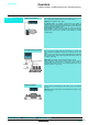
General Counters Totalising counters, predetermining counters and totalising timers Applications Totalising counters These are used for counting events from electrical pulses or contacts. The value is displayed and updated in increments on each new pulse.
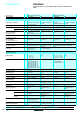
Characteristics Counters Totalising counters, predetermining counters and totalising timers Type of device Type of display XBK-T totalising counters mechanical LCD XBK-H totalising timer mechanical LCD EN 50081-2, EN 50082-2 EN 50081-2, EN 50082-2 EN 61010 UL, CSA (pending) except XBK-T60000U00M UL, C-UL (pending) EN 50081-2, EN 50081-2, EN 50082-2 EN 50082-2, VDE 0435 EN 61010 Environment Conforming to standards Product certifications Temperature UL, CSA (pending) UL, C-UL (pending) Operation °C
Characteristics Counters Totalising counters, predetermining counters and totalising timers Type of device Type of display XBK-P5 Mechanical XBK-P6 LED or LCD Environment Conforming to standards EN 50081-2 and EN 50082-2, EN 61010 Product certifications XBK-P5pppDppM : CSA (pending) XBK-P5pppUppM : UL/CSA (pending) UL, C-UL (pending) Temperature Operation °C - 10…+ 50 0…+ 50 Storage °C - 40…+ 85 - 20…+ 70 Degree of protection according to IEC 529 IP 40 IP 65 Vibration resistance accord
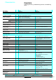
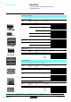
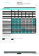
References Counters Totalising counters, predetermining counters and totalising timers Totalising counters With mechanical display Supply Number voltage of display digits V $ 24 XBK-T50000U Counting frequency Type of reset to zero Reference Weight Hz kg 5 20 Manual XBK-T50000U10M 0.100 6 25 None XBK-T60000U00M 0.030 25 Manual XBK-T60000U10M 0.150 7 20 None XBK-T70000U00M 0.100 8 25 None XBK-T80000U00M 0.150 $ 48 5 20 None XBK-T50000U08M 0.
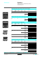
References Counters Totalising counters, predetermining counters and totalising timers Subtracting predetermining counters with mechanical display Supply voltage Number of display digits V $ 24 Counting frequency Number of presets Type of reset Reference Hz 5 25 Weight kg 1 Manual XBK-P50100D10M 0.200 Manual and electric XBK-P50100D20M 0.240 Adding predetermining counters with mechanical display / XBK-P50100D 0M $ 24 5 25 1 Manual XBK-P50100U10M 0.
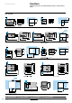
Dimensions Counters Totalising counters, predetermining counters and totalising timers XBK-T50000U//M XBK-T70000U00M Flush-mounting XBK-T60000U00M Flush-mounting e 31 27 20 14,2 e 33,7 27+0,2 38,5 e : panel thickness, 1 mm < e < 2.5 mm.
Connections Counters Totalising counters, predetermining counters and totalising timers XBK-T50000U//M XBK-T70000U00M XBK-T80000U00M XBK-T60000U1/M + -/+ XBK-T60000U10M -/+ 1 1 2 2 – + XBK-T80000U00M 1 1 2 2 – XBT-T81030U33E XBK-H81000033E + / / XBK-P50100D 0M XBK-P50100U 0M + PNP 4 3 2 1 1 Reset Count 0V Keylock 31 2 1 22 21 31 2 20 32 – 32 21 + NPN 4 3 2 1 Reset Count 0V Keylock 20 22 – – XBK-P6 $ 24 V //30G3/E $ 24 V + + Black 2-wire sensor/detector type XS, X
Compatibility Counters Totalising counters, predetermining counters and totalising timers Electromechanical technology Totalising counter XBK-T5, XBK-T7 Input Input $ 24 V " 115 V 70 mA 22 mA 1.5 W 2.5 VA Type Supply voltage Current consumption Power Input $ 48 V 32 mA 1.5 W Inductive proximity sensors/ 3-wire photo-electric detectors XBK-T6, XBK-T8 Input $ 24 V 110 mA 2.5 W XBK-T6 compact Input $ 24 V 6 mA 0.155 W Input " 115 V 24 mA 2.
Compatibility Counters Totalising counters, predetermining counters and totalising timers Electronic technology Type Supply voltage Voltage Resistance Current Totalising counter + totalising timer XBK-T8, XBK-H8 Input Reset to zero – – XBK-P6 Inputs Relay output Solid state output – – $ 24 V State "1" >$ 5V State "0" < $ 0.7 V 50 kΩ – State "1" >$8V State "0" <$2V – 10 mA max State "0" < $ 0.
Presentation, description “Zelio Logic” smart relay Presentation / / / / The “Zelio Logic” smart relay is designed for use in small automated systems. It is suitable for use in both industrial sectors and commercial premises. Its compactness and ease of setting-up provide a competitive alternative to basic cable logic or specific card solutions. The ease of programming, ensured by the universality of the contact language, meets all automation requirements and also the needs of the electrician.
Presentation, description (continued) Contact language Function “Zelio Logic” smart relay Electrical scheme Ladder language Zelio smart relay symbol Ix 21 13 Contact or 14 22 or N/O N/C or Notes I corresponds to the real state of the contact connected to the input of the smart relay. i (or I) corresponds to the inverse state of the contact connected to the input of the smart relay. ix The coil is energised when the contacts to which it is connected are closed.
Functions Functions “Zelio Logic” smart relay The Zelio Logic smart relay comprises - 8 or 10 Time delay function blocks, each with 8 choices of parametering, - 8 or 10 Counter function blocks, - 4 Clock function blocks, each comprising 4 channels. - 8 Analogue function blocks, each with 7 choices of comparator parametering, - 4 or 6 text function blocks (see Zelio Soft software page).
Functions (continued) “Zelio Logic” smart relay Modes Parameter entry mode This mode allows centralising of all the parameters relating to unlocked function blocks that are used in the programme. Any of these parameters can be modified. In this example, the user can modify : - the preset time delay value T1, - the preset counter value C1, - the reference voltage of analogue block A1, - the parameters of clock block n°1 (date, time zones).
Description “Zelio Logic” smart relay “Zelio Soft” software for PC (V1.5) 816721 “Zelio Soft” software enables : - inputting of control schemes, - detection of any programming errors by means of its coherence test function, - inputting of messages for display on the “Zelio Logic” smart relay, - testing of programmes, with or without the smart relay connected to the PC.
Description “Zelio Logic” smart relay Zelio Soft software for Pocket PC L N I1 I2 I3 I4 I5 I6 Del. Ins.line z1 z4 z2 z3 Esc. O1 O2 O3 Sel./OK O4 + – O1 I1 I2 I3 I4 I5 I6 IB IC O2 O3 O4 L N I1 I2 I3 I4 I5 I6 I7 I8 Del. I9 IA IB IC Ins.line z1 z4 z2 z3 Esc. O1 O2 O3 Sel.
Characteristics “Zelio Logic” smart relay Environmental characteristics Approvals UL, CSA, C-TICK, GL Degree of protection IP 20 Temperature Operation Readability of display Storage °C °C °C % - 20...+ 55 conforming to IEC 68-2-1 and 68-2-2 0...+ 55 conforming to IEC 68-2-1 and 68-2-2 - 25...
Characteristics (continued) “Zelio Logic” smart relay Discrete $ 24 V input characteristics SR1-////BD I1 to IA Smart relay type Input SR1-///BD IB and IC SR1-///JD Voltage Current V mA Screw terminals 24 12 3 3 Screw terminals 24 12 0.62 0.21 State 1 Voltage Current V mA ≥ 15 > 1.8 ≥ 6.5 > 1.6 ≥ 9.9 0.16 ≥ 9.9 0.16 State 0 Voltage Current V mA <5 < 0.5 < 6.2 < 1.5 <5 0.08 <5 0.08 kΩ 8 4 38 57 ms ms 0.3 (fast)…3 (slow) 0.
Characteristics (continued) “Zelio Logic” smart relay Relay output characteristics (screw terminal connections) (1 / SR1-B121JD, SR1-/1/1BD, SR1-/101FU, SR1- 101B 4 Smart relay type Number of outputs Without common potential V Operating limit values $ 5…150, " 24…250 N/O Contact type A 8 V A V A V A V A mA 24 1.5 24 V L/R = 10 ms 0.6 230 1.5 230 0.9 10 No-load Hz 17 V - 5 mA Failure rate for 100 million operating cycles : 1 10 At le Hz 0.
Curves “Zelio Logic” smart relay Electrical durability of relay outputs (in millions of operating cycles) (conforming to IEC 947-5-1) d.c. loads DC-12 (1) DC-13 (2) 3,0 Millions of operating cycles Millions of operating cycles 1,4 2,5 48 V 2,0 24 V 1,5 1,0 0,5 L/R = 10 ms 48 V 1,2 L/R = 10 ms 24 V 1,0 L/R = 60 ms 48 V 0,8 L/R = 60 ms 24 V 0,6 0,4 0,2 0,0 0,0 0 0,5 1 1,5 0,1 2 0,2 0,3 0,4 0,5 0,6 0,7 0,8 a.c.
References “Zelio Logic” smart relay Smart relays 816716 Number of I/O Discrete inputs Outputs Clock Remanence function (1) Reference 8 I $ 12 V (2) 4 O relay Yes Yes (3) SR1-B121JD 0.290 10 6 I $ 24 V 4 O relay No No (4) SR1-A101BD 0.290 12 8 I $ 24 V (2) 4O relay Yes Yes (3) SR1-B121BD 0.290 4 S transistor Yes Yes (3) SR1-B122BD 0.290 12 I $ 24 V 8 O relay No No (4) SR1-A201BD 0.350 12 I $ 24 V (2) 8 S relay Yes Yes (3) SR1-B201BD 0.
References “Zelio Logic” smart relay 530034 Power supply (1) Input voltage Nominal output voltage Nominal output current Reference Weight kg 100…240 V 47…63 Hz $ 12 V 1.9 A ABL-7RM1202 0.180 $ 24 V 1.4 A ABL-7RM2401 0.182 Separate components ABL-7RM2401 Description Reference Weight kg EEPROM back-up memory SR1-MEM01 0.001 Zelio Soft software for PC Description Reference Smart relay-PC connecting cable length 1.8 m SR1-CBL01 0.
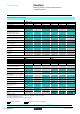
Dimensions, Schemes Dimensions “Zelio Logic” smart relay ///// Smart relays SR1-SR1- 90 100 110 45 68 42,5 28 b 55,4 a 5,3 / //// / //// a 72 126 SR1- 1 SR1- 2 b 60 110 Schemes // 3-wire sensors on SR1- 1BD, SR1-B121JD Analogue inputs on SR1-B121BD, SR1-B121JD on SR1-B201BD 0-10 V ANALOG. (1) + Ca / Ta 1 (1) + SR1-B121BD 24 V SR1-B121JD 12 V BL BN BL Q1 (1) Ca / Ta 2 SR1-B121BD 24 V SR1-B121JD 12 V BN I1 I2 I3 I4 I5 I6 IB IC Q2 Ca / Ta 1 BK BK + 0-10 V ANALOG.
Schemes (continued) “Zelio Logic” smart relay SR1-/1 1BD, B121JD / SR1-B122BD + (1) + SR1-/201BD (1) (1) 24 V + 24 V + I1 I2 I3 I4 I5 I6 IB IC + I1 I2 I3 I4 I5 I6 IB IC Q3 + Q4 (2) L /+ or Q2 U (3) Q2 (2) + 12...240 V 50 / 60 Hz 12...125 V Q1 Q3 Q4 Q1 L /+ 24 V or 12...240 V 50 / 60 Hz or N/ U I5 I6 I7 I8 Q2 Q3 Q4 L /+ or Q7 Q8 U (3) 12...240 V 50 / 60 Hz or (3) U (3) 12...