(without price) SF-5590SY/5790SY/5990SY SF-5590SY PLUS/5790SY PLUS/ 5990SY PLUS (ZX-455) SEP.
CONTENTS 1. SPECIFICATIONS ................................................................................................ 3 2. GENERAL GUIDE ................................................................................................ 5 3. DATA COMMUNICATIONS ...............................................................................12 3-1. DATA TRANSMISSION FROM A UNIT TO ANOTHER UNIT ...................13 3-2. DATA TRANSMISSION BETWEEN A UNIT AND PERSONAL COMPUTER USING FA-128 ...... 13 4.
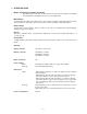
1. SPECIFICATIONS Model: SF-5590SY/SF-5790SY/SF-5990SY * PC LINK software and cable for data transmission (FA-128) are added to SF-5590SY PLUS/5790SY PLUS/5990SY PLUS. See to 9. PARTS LIST.
Current consumption: Main (Input voltage = 3.0 V): Telephone top menu (Backlight doesn't shine)4.3 mA (TYP.)/5.3 mA (MAX.) Telephone top menu (Backlight shine)27 mA (TYP.)/38 mA (MAX.) OFF (Using Mask ROM: regular)90 µA (TYP.)/130 µA (MAX.) OFF (Using Flash ROM: irregular)120 µA (TYP.)/160 µA (MAX.) Back-up (Input voltage = 3.0 V): 2.4 µA (TYP.)/10 µA (MAX.
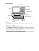
2. GENERAL GUIDE Mode key Memory keys Display 10-key pad Operator keys Display Change key ON/OFF key Mode keys Cursor keys Light key Scroll/Search keys Function key ESC key Alpha keyboard ■ Display When lighting is dim, you can turn on an EL (electro-luminescent) backlight for easier viewing. To turn on the EL backlight There are two ways to turn on the backlight of the display. Pressing LIGHT causes the backlight to turn on for about 15 seconds, and then turn off automatically.
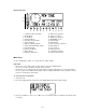
Display Indicators ~ B N 1 1 2 3 4 5 6 7 8 9 0 A B 2 3 4 5 Telephone Directory Mode Memo Mode To Do Mode Reminder Mode Schedule Keeper Mode Calendar Mode Expense Manager Mode Home Time/World Time Mode Calculator Mode Conversion Modes Game Modes Indicates data above 6 7 C D E F G H I J K L M N 8 9 0 A SHIFT key operation Upper-case input CODE key operation NEW/EDIT screen Index display Data display Snooze feature activated Daily alarm on Key sound on Memory locked Low battery warning Indicates
When to press Y for “yes” • When this is the first time you are using the unit. • When you want to reset the unit and clear all data and settings. • When you are resetting the unit after a data error (page 18). 1. Press Y in response to the message that appears on the display when you start the all-reset operation. 2. Press OK to reset the Digital Diary or ESC to abort. • At this time the message “SET TIME!” appears. • After about two seconds, the Home Time screen appears. 3.
■ Power Supply Your Digital Diary is powered by two AAA-size alkaline batteries, and its memory is protected by a single CR2032 lithium battery. Low battery Warning Failure of anything to appear on the display after you turn on power or appearance of the low battery message, “MAIN BATTERIES WEAK! REPLACE THEM! UNIT WILL NOT TURN ON AGAIN!” (followed by the display turning off in about 10 seconds) normally indicates that main battery power is low.
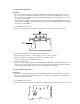
To replace the main batteries Important! • Do not remove the main batteries from the Digital Diary while the back-up battery is removed. • Be sure to replace both batteries with two new ones. Do not mix an old battery with a new one. • Be sure to press the START button after loading main batteries for the first time or if the previous set of batteries went dead. • Replace batteries only when low battery power is indicated by failure of the Digital Diary to turn on when you press the ON key.
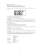
3. Insert a thin, pointed object into (A) and remove the old battery. (A) 4. Load a new battery into the compartment, making sure that its positive side is facing up (so you can see it). 5. Replace the battery compartment cover and secure it with its screw. • Take care that you do not overtighten the screw. ■ Turning Power On and Off Press ON/OFF to turn power on and off. Important! • If nothing appears on the display when you turn on power, it means that the main batteries are low.
■ Key Input Sound When the key input sound is turned on, your Digital Diary emits a beep each time you press one of its keys. To turn key input sound on and off 1. Press SHIFT FUNC and then select “Key tone.” Currently selected setting 2. Use O and P to turn the key input sound on and off. • The indicator is on the display while the key input sound is on. 3. Press OK to quit.
3. DATA COMMUNICATIONS You can transfer data between two CASIO SF-5590SY,SF-5790SY, or SF-5990SY units, or between your Digital Diary and a personal computer only. You cannot exchange data with any other CASIO Digital Diary model. Data communications can be performed while in the Telephone Directory, Memo, Schedule Keeper, Calendar, To Do, Reminder, or Expense Manager Mode. Data synchronizing helps you to make sure that the data in your PC and your Digital Diary are always up to date.
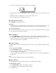
3-1. DATA TRANSMISSION FROM A UNIT TO ANOTHER UNIT Performing the following procedure, you can transfer the data from a unit (S) for sending to another unit (R) for receiving without entering password even if unit (S)'s data are protected by password. Remarks: 1. The units should be the same models because these units should have the same memory capacity and functions. 2. Press ESC button if you abort any operation. PROCEDURE 1 Connect two units using the SB-63 cable as described with the previous page.
● PROCEDURE 1 After setting up FA-128 PC LINK software to your PC in accordance with User's Guide, connect SF-5590SY/5790SY/5990SY to PC using cable for data transmission. 2 Open FA-128 PC LINK software. 3 Select Options in Menu Bar, then Default Digital Diary... . 4 Select available Digital Diaries (for example, SF-5590SY), then OK. 5 Select Casio, then Synchronization Setup... . 6 Perform Setup for Synchronization in accordance with User's Guide.
4. OPERATION CHECK REMARKS: 1. Executing this check, the data stored in this Digital Diary are deleted. So if you won’t delete this important data, you should store its data in another Digital Diary (SF-5590SY/5790SY/ 5990SY) referring to the item 3. Data communications in this manual. 2. You cannot put out the light from EL while executing this check. ● LCD CHECK 1 Press RESET button on the rear panel while pressing OK button on the front panel. LCD display appears as shown right.
7 Wait about 45 ~ 50 seconds. In case of SF-5590SY, LCD display ROM TEST ROM OK RAM TEST 1 2 8 K OK In case of SF-5790SY, LCD display ROM TEST ROM OK RAM TEST 1 2 8 K OK 2N D RAM TEST 1 2 8 K OK , or LCD display ROM TEST ROM OK RAM TEST 2 5 6 K OK In case of SF-5990SY, LCD display ROM TEST ROM OK RAM TEST 5 1 2 K OK ● KEY CHECK 8 Press OK button. LCD display KEY TEST 9 Press any button. For example, press TEL button.
C Press 2 button on any unit (A). This unit’s LCD display 2 ECHO (OK) D Then press 1 button on another unit (B). Another unit’s LCD display 1 COMM 2 ECHO OK In case of NG, LCD displays a letter “FAIL”. If “OK” was displayed, another unit (B) transmitted data to any unit (A). E Pressing ESC buttons on the both units, return to the condition described in the item B. LCD displays on the both units are the same as display shown in the item A .
5. ERROR MESSAGES Data Error Message The data error message appears whenever the Digital Diary’s internal check discovers a problem with data stored in memory. Appearance of the data error message indicates that you must perform the all-reset procedure to correct the problem. Start out with the procedure under “To start the all-reset operation” on page 6, and continue with the procedure under “When to press Y for “Yes” on page 6”.
CPU 6. SCHEMATIC DIAGRAMS 6-1.
6-1.
6-1.
6-1.
COM. PORT BUZZER 6-2.
POWER SUPPLY 6-2.
6-2.
7. LSI PIN FUNCTION CPU (LC868016A): U1 Pin No. Name I/O Function 1 VDD I Power supply for this CPU 2~65 S1~48,C1~16 O Common signals to LCD 66 V1 O 67 V2 O 68 V3 O Bias power supply to LCD 69 V4 O 70 V5 O 71 VLCD O Power supply to LCD 78 VSS — Ground for this CPU 80 P41 O Clock for LCD driver LSI(U2, U3:LC868900) 82 P43 O Signal to LCD driver LSI(U2, U3:LC868900)(AC voltage is supplied to LCD by this signal.
8. DISASSEMBLY 1 Remove two screws then remove the battery cover. 2 Remove three screws. 3 Open the unit and remove two screws behind the display plate.
4 Remove Lower cabinet (keyboard) and keytop. Keytop Lower cabinet (keyboard) 5 Remove Rubber key, knob and jack cover. Rubber key Jack cover 6 Desolder the wire connected to the buzzer on the Lower cabinet (keyboard) from keyboard PCB ass’y. Knob 7 Remove Lower cabinet (display).
8 Remove screws on PCB shown above then remove PCB ass’y. Main PCB (9 screws) Keyboard PCB (11 screws) 9 Separate upper cabinets. REMARK: Heat seal and wires must be placed inside of the hinge in order for the Lower cabinet (keyboard) to fit into place. If heat seal and wires are placed improperly, they are damaged.
9. PARTS LIST N Item Code No.
N N N N N N N N N N N N N N N N N N N N N N N N N N N N N N N N N N N N Item Code No.
10.
MA0900571A